I will return early in 2015 with updates and a run through of the cleaning of the F3.
Have a good break and festive greetings to everyone!
I will return early in 2015 with updates and a run through of the cleaning of the F3.
Have a good break and festive greetings to everyone!
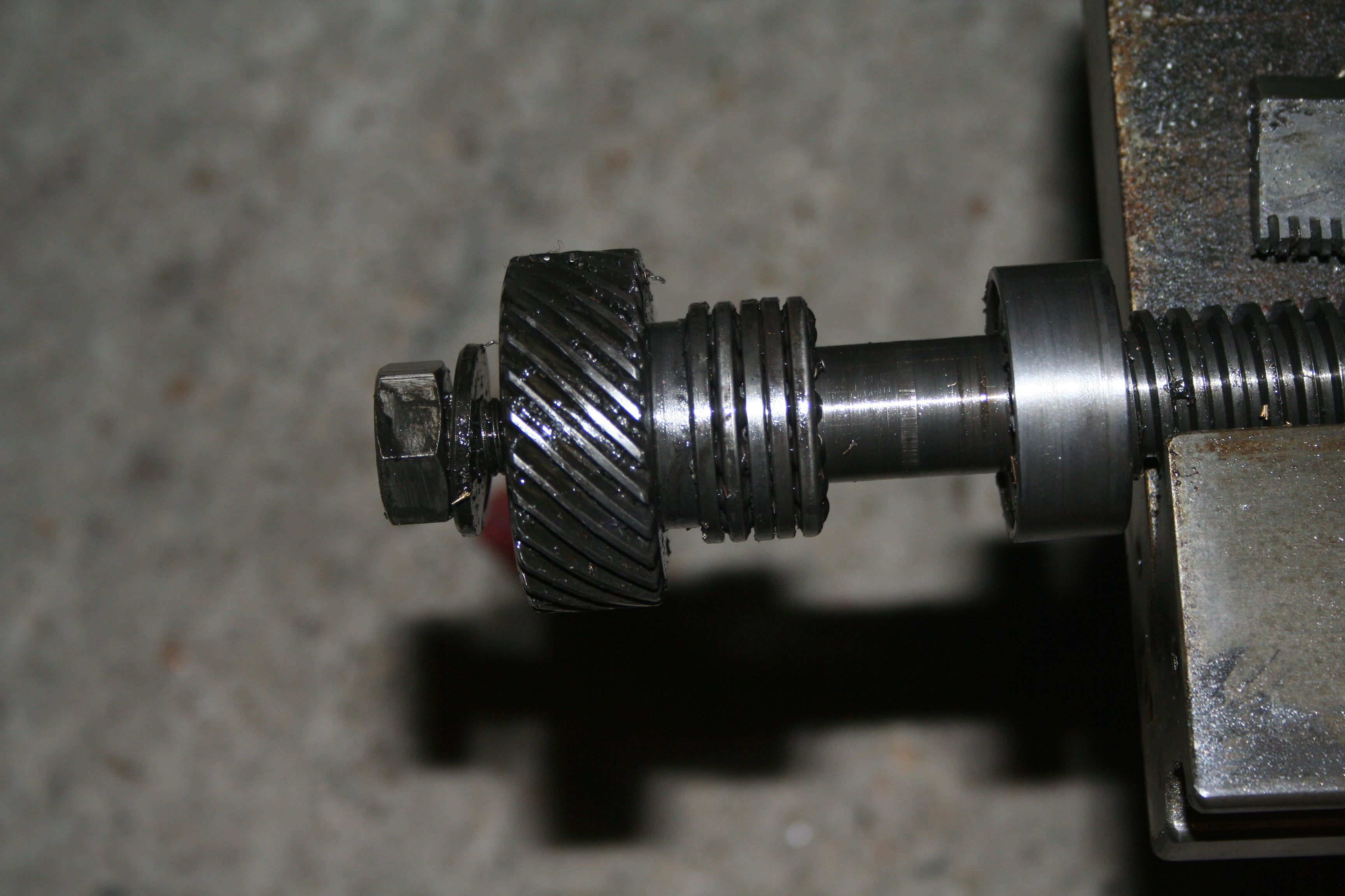
Last night I lifted the upper casting higher so I could get an air impact wrench on the lower nut. It was undone in half a second and I didn’t even need to hold the z-axis screw with anything. (I’ll use the same technique for tightening up!) It was then a simple matter of removing the bearings and collar (using a pin wrench) and lifting the whole unit away from the casting. I made a careful note of the order in which the bearings etc came off and reassembled them onto the screw for cleaning later on.
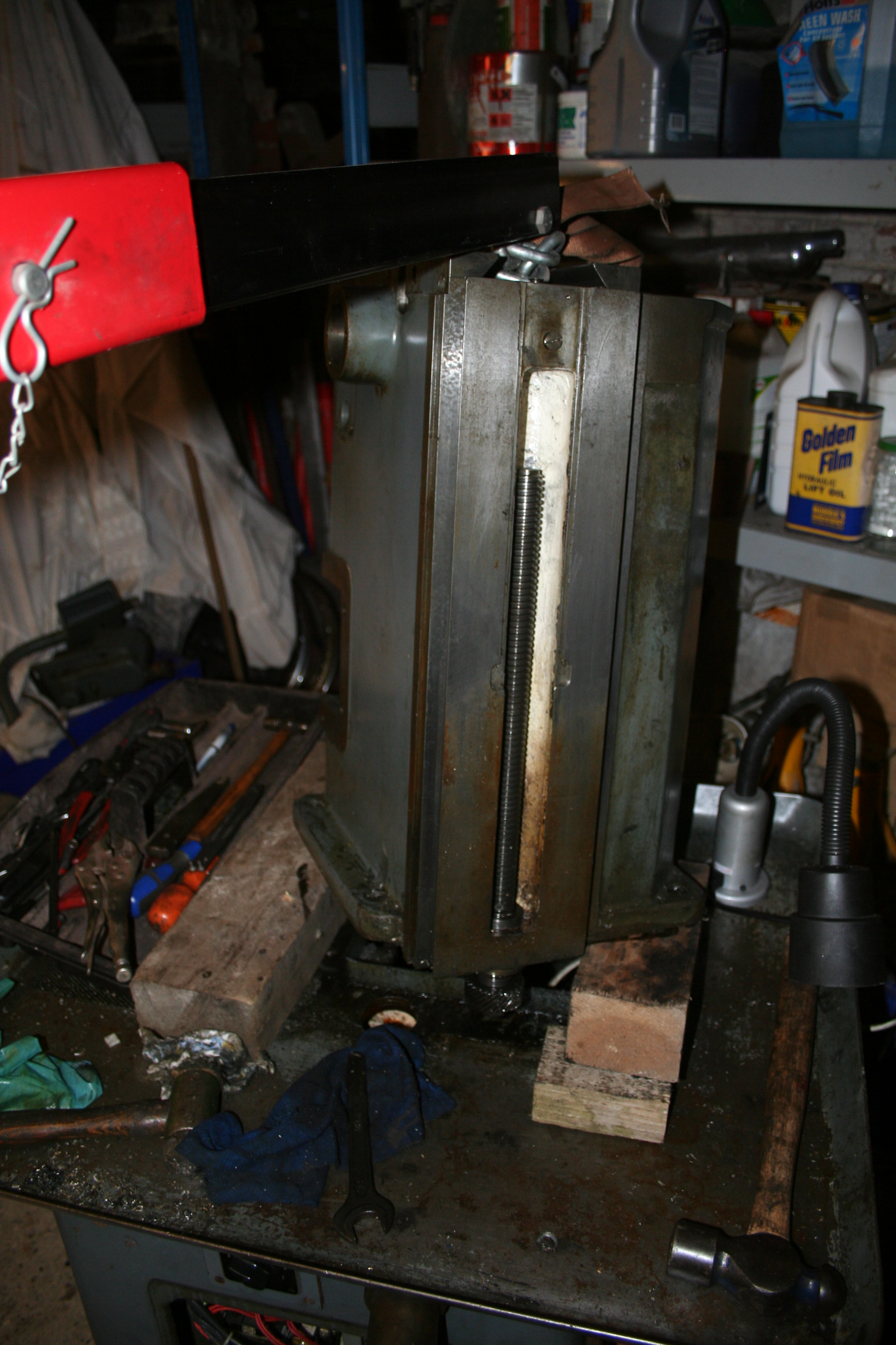
The upper casting is now bare (except for a few oil nipples) and is ready for a good clean as does the drip tray.
The lower casting oil well is half full of swarf and oil and will need some heavy duty cleaning.

The Y-Axis screw is within a large collar that is mounted into the lower casting at an angle. There are 2 large grub screws that hold this in place. Well, only the lower one on my F3. Even removing the grub screw it seemed pretty much stuck. Some gentle persuasion with a wooden block and hammer got it shifted.

All that now remains to be done is:

Once the above has been done, I can move on to the next section of cleaning, inspection and refurbishing before the re-assembly.
A little warmer this evening!
OK, I’m now ready to remove the top main column from the base & tray. I just need to get the hoist in position. I also have no idea where to sling the ropes!

Its far too cold to get on my hands and knees to attempt to remove the motor but a quick look has me puzzled – what is the best way to do this?
With the hoist in place I gingerly raised the main casting! What appeared to be happening was that the boss for the z-axis spindle was rusted to the drip tray. 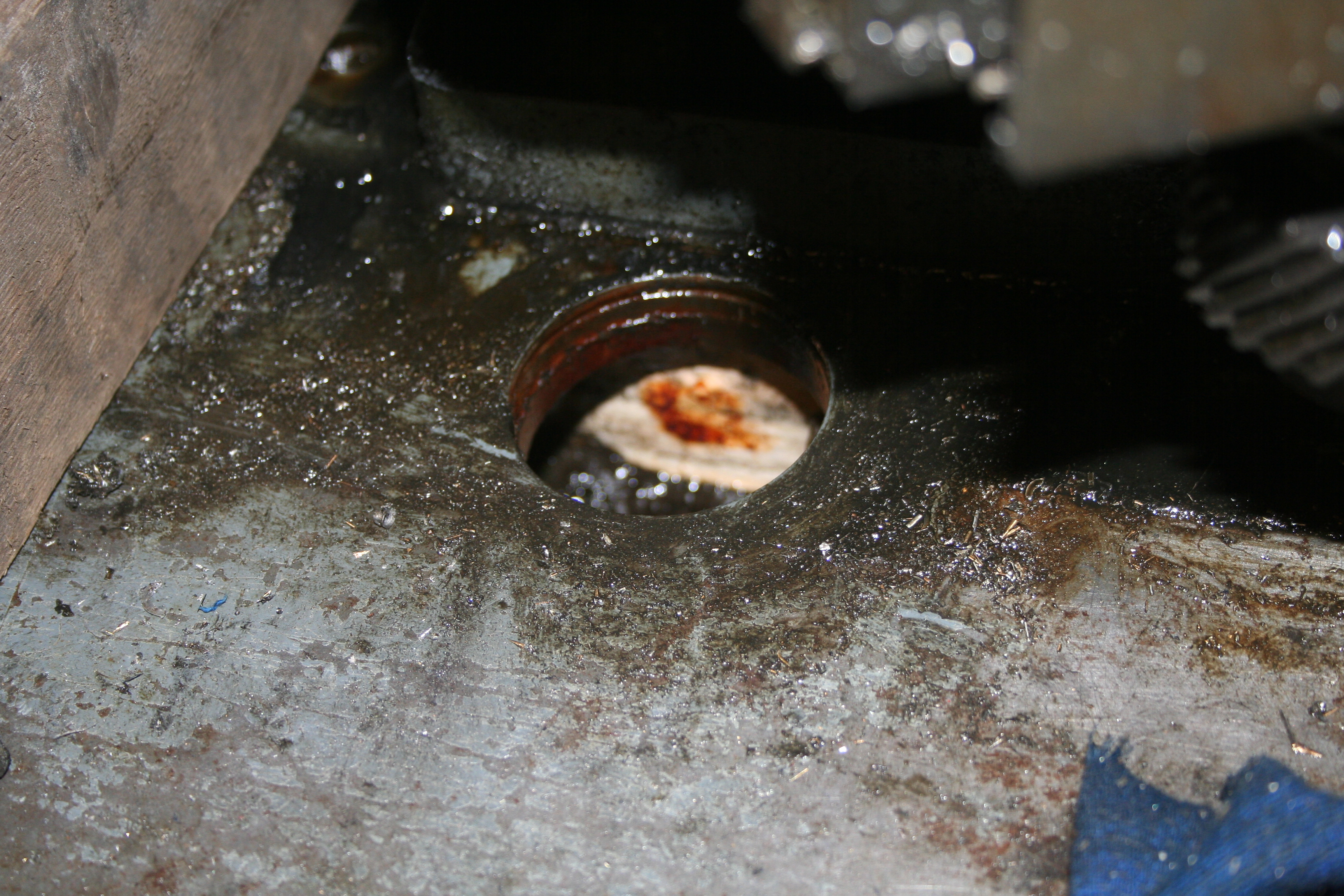
It took a little while to work this out as the tray seemed well fixed at this point. Anyway a block and a sharp knock and the drip tray dropped clear. Above is the rusty crud around the hole holding it all together.
So, how do I now remove the nut at the bottom of the screw?

So below is the photo after removing the z-axis carriage.
Last night saw the removal of the auto-feed gearbox. This should have been a simple operation but necessitated me removing the pulley from the shaft – and of course, it didn’t want to budge. Now under normal circumstances it would be easy to put on a puller and then just ease the pulley of its keyed shaft. However, there is no room in the belt ‘cavity’ and so I ended up using wedges behind it. After a little encouragement it moved and I was then able to remove the gearbox with a little turning and twisting (its quite a close fit!).
Thr cables have been now removed from the light & start/stop pod and the arm removed.
Here are a few more photos:


I’m not sure yet how the top casting (main body) comes away from the base/drip tray. So for nothing better to do, I removed the z-axis nut.

So, tonight’s teaser – what the heck is this screw for?:

I really can’t see what purpose it serves!
After a little thought, I established that there was a collar on the end of the screw – something made to allow the dual dials to work. This covered over the original thread of the screw that is used on single dials. With the pin drifted out and the grub screw loosened, then the collar just came away with a gentle tap.

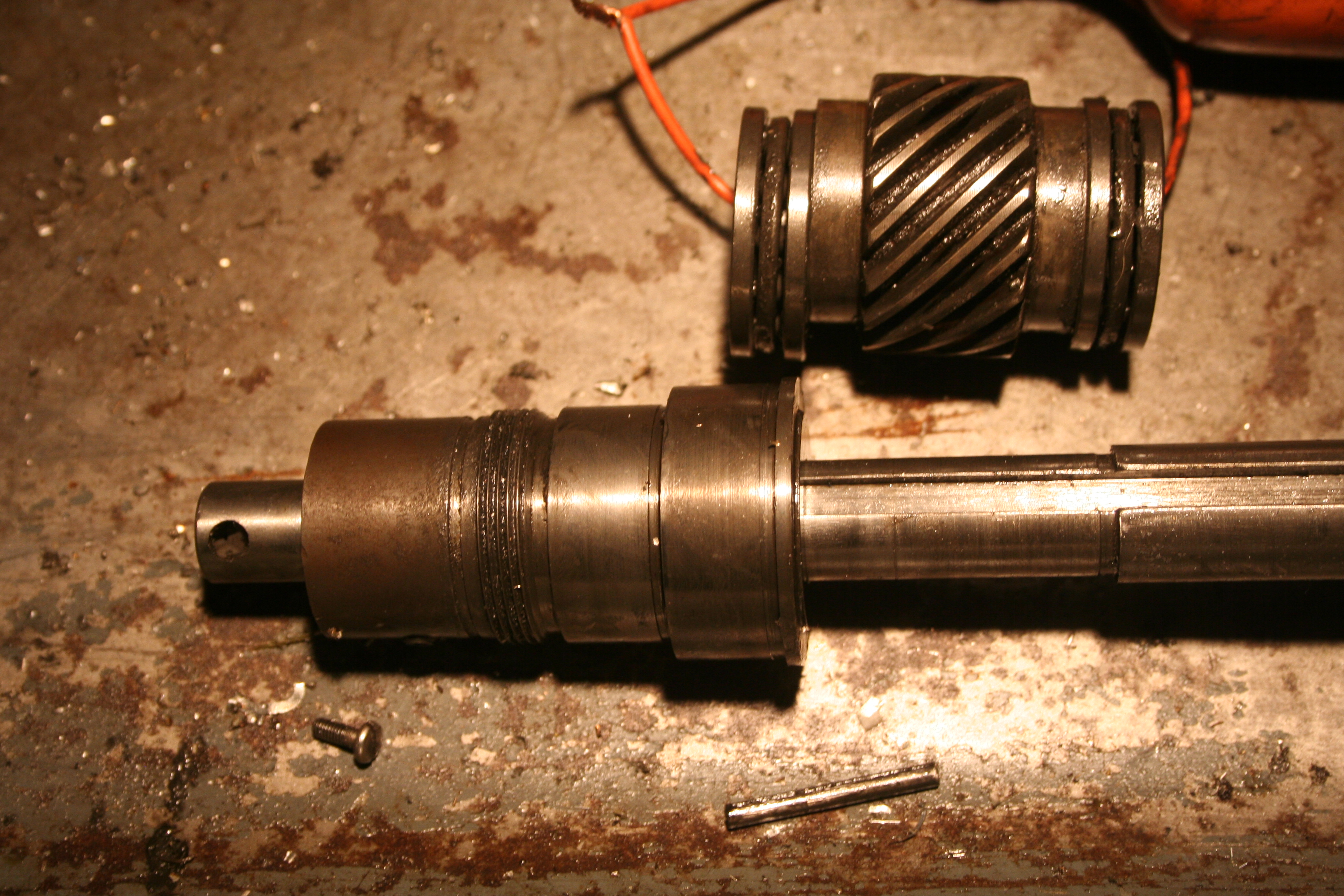
The screw was then pulled out of the carriage towards the opposite end. I held my hand under the gear in the carriage for fear it would fall away but the grease and dirt held it all in place. What I didn’t spot was how the bronze key (a 2nd key next to the one pinned to the helical gear) was held in place – probably retained in the gear / bearing cluster. I’m sure it will all become clear on the re-assembly!

Next, we move onto the Z-axis. From what I can see, I just need to remove the carriage from the z-axis nut, remove the jib strip and it should lift off. And indeed, that is what was required. The nut needed to be moved ‘back’. To do this, I removed the central cap head screw and then put it back a few turns and gently tapped it. This moved it away from the nut and the cap head screw stopped it falling to the drip tray. All I needed to do was to lift the carriage up off the machine.
Next item to remove was the top dials for the Y axis – easy now I know!

Well, the roll pin on this one is buggered! So that can wait.
My next task was to remove the auto traverse gearbox….

This will need a little thought! As removing the bolts does not allow it to come away from the main casting! – the pulley is in the way, I think.
I have now managed to remove the carriage. Quite simple with the other endplate onbolted.
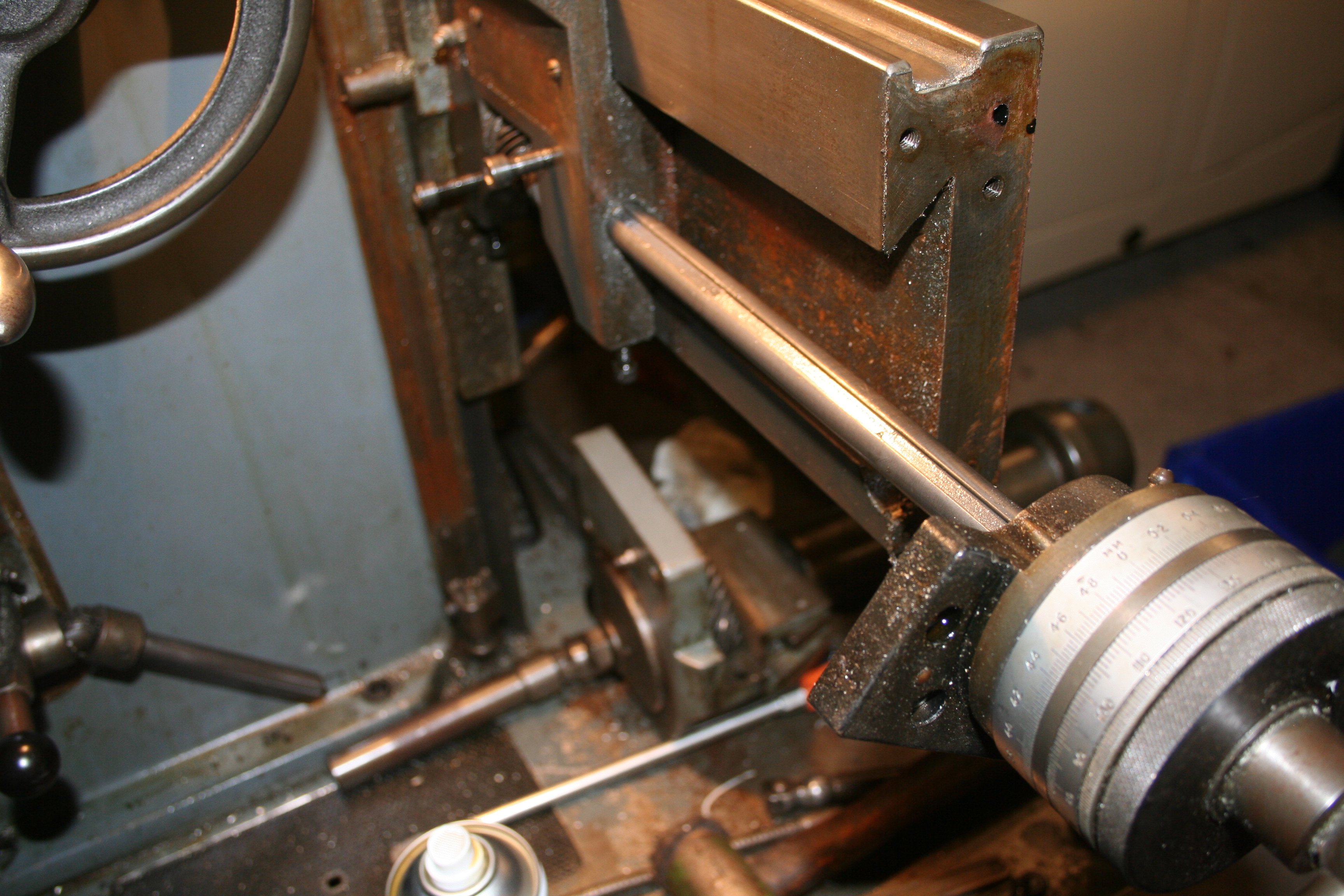
It is now possible to just slide off the carriage in the opposite direction.

And voila, the carriage is now off the machine.
OK, with that done, I now need to withdraw the main screw. Whilst deliberating why the screw will not come out, I decided to remove the dials etc. All straight forward up to this point:
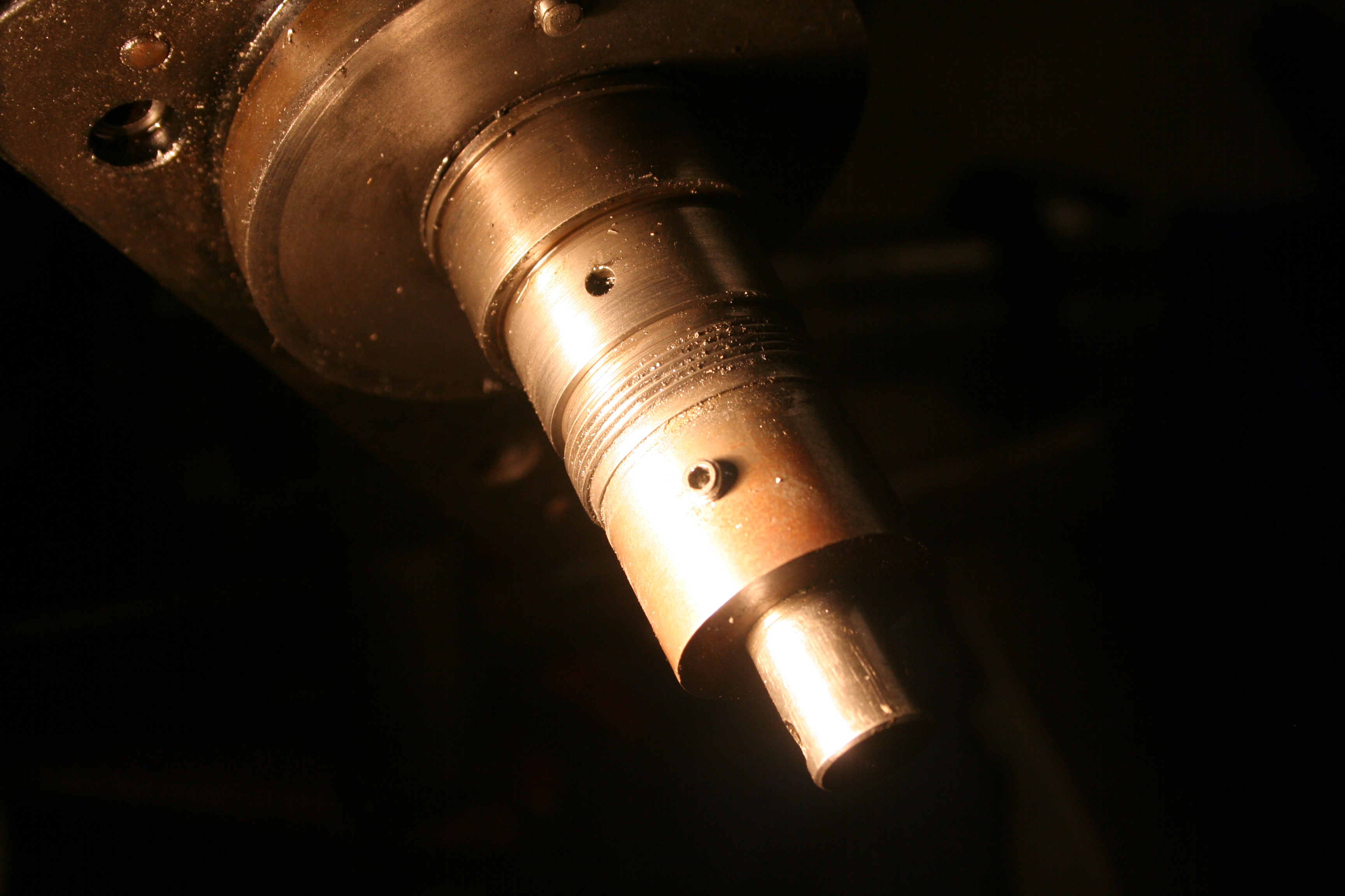
So, looking at my exploded diagram, I’m none the wiser. My main screw has a keyway along part of its length and the keyway insert seems to be stopping the screw coming away from the body and helical gear.
 I’m also wondering if this ‘pin’ is stopping things. More deliberation and wine, I think!