Joining her back together!

It has taken a while to get to this stage but I have been awaiting my grease and replacement bearings. I ended up choosing CV-2 synthetic grease from RedLine:

IMG_0669

It’s not Mobil SHC120 but very similar in specification. In short, all suppliers in the UK wanted to sell me 32 gallons drums of the stuff – not exactly what I was after! I have used Redline products before (notibly in a Ferrari gearbox!) and was very pleased with their product. Armed with this grease, I replaced the lower z-drive bearings with new SKF ones and then put it all back together with the CV-2 grease. Lowering it onto the base was fun as I needed to centralise it on my own. Once in place, it was necessary to use the large cap head screws to ensure it was fully bolted down correctly and to be perpendicular.

With the upper casting lowered onto the main base, it is starting to look like  complete machine again.

IMG_0668

There is still a lot to do but I’m getting there! Currently I am repainting the main head and vertical drive head. The doors will also need blasting and priming.

The most labour intensive job is removing tarnish from the exposed metal parts – more info on that next time!

Progress after a pause!

I’m not sure why I thought the coolant pump was not accessible when the drip tray was fitted! Because of this thought, I didn’t want to progress until the pump was repaired – duh! As you ca see below – it is easy to replace / insert the pump. It was probably because everything was so dirty!

The oil pump bearing is a graphite carbon seal affair similar to those used in car water pumps. I have ordered a suitable replacement that will require a little fitting but should do the job.

No stopping me now! IMG_0666

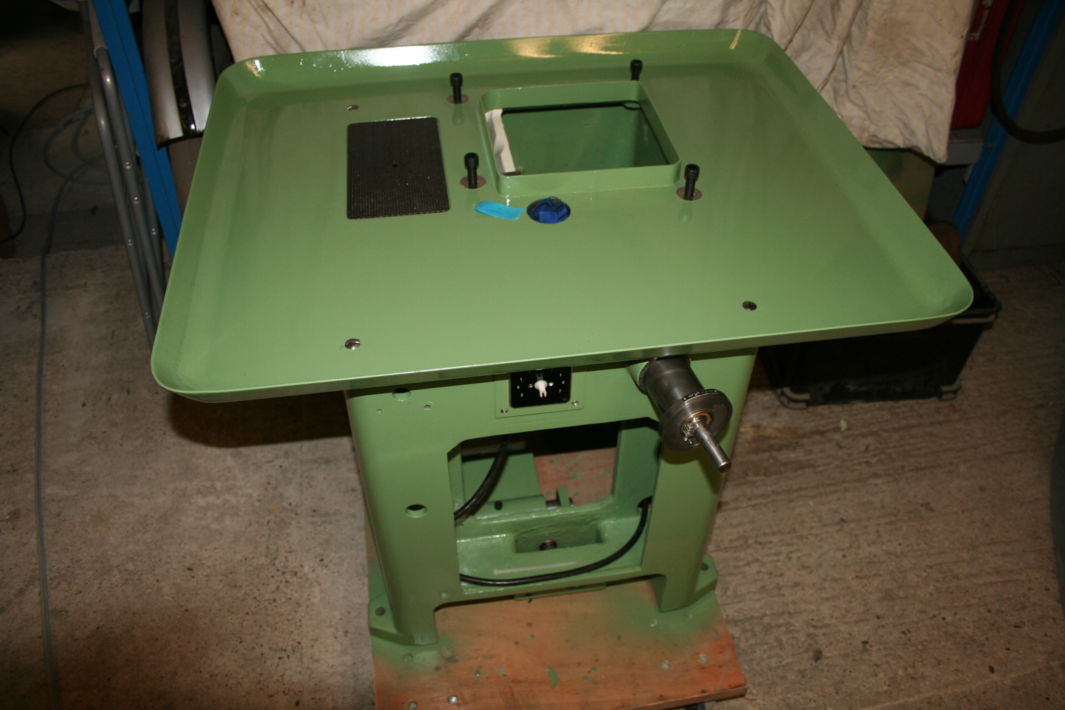
Anyway, the tray is now fitted. Not much to explain here – all very straightforward. As there is quite a bit of bare metal under the tray, I pup a little grease on top of the casting to protect it. Where relevant, ‘copaslip’ was used to enable seize free assembly.

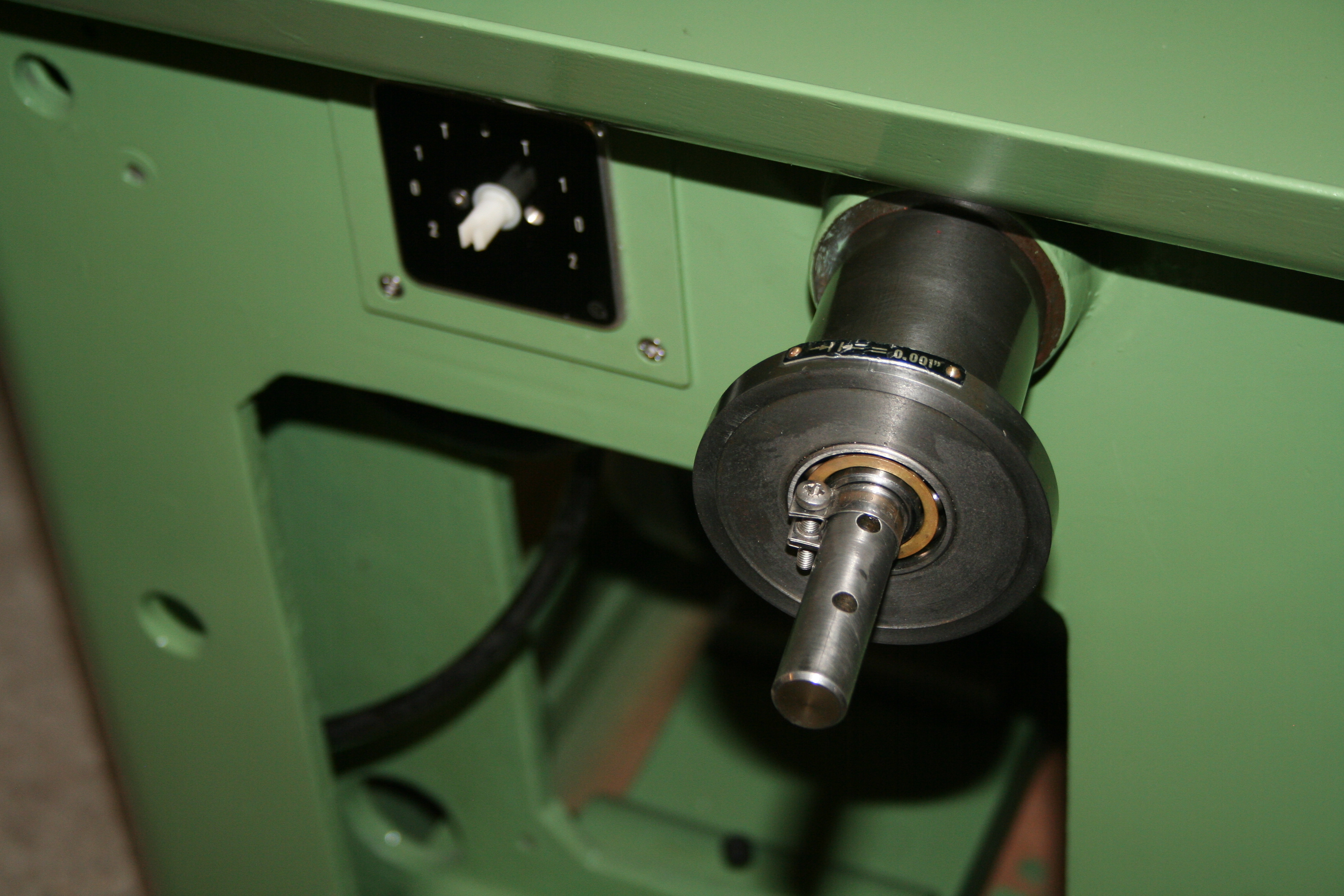
The z-axis input shaft is fitted but not greased up yet. This can be removed easily when all is in place as there is no locking nut on the top part of the casting – although there is a threaded hole for one. (There was no fitting there when I took it all apart)

IMG_0656

The motor is now wired to the switch and in turn I have left a trailing lead to put to the inverter. The Ghilmetti switch had feint marking on the terminals to allow fitting of cables. Thus it was an easy job (once I knew) to run the 6 cables from the switch to the motor and the 3 in readiness for the inverter.IMG_0659

I may, however, use a shorter lead and fit the inverter in the void where the old electrics were. there is plenty of space and a simple alloy case will protect the unit from any stray oil or swarf. Wiring from here to the ESTOP and speed control will need installing. I’m still thinking about the location of the inverter….

IMG_0665

The main motor pulley took a bit of persuasion to be reunited with the shaft. I need to centralise the motor to the pulleys once the top pulley is in place as at the moment the motor is fairly free to slide along its locating shafts.IMG_0658

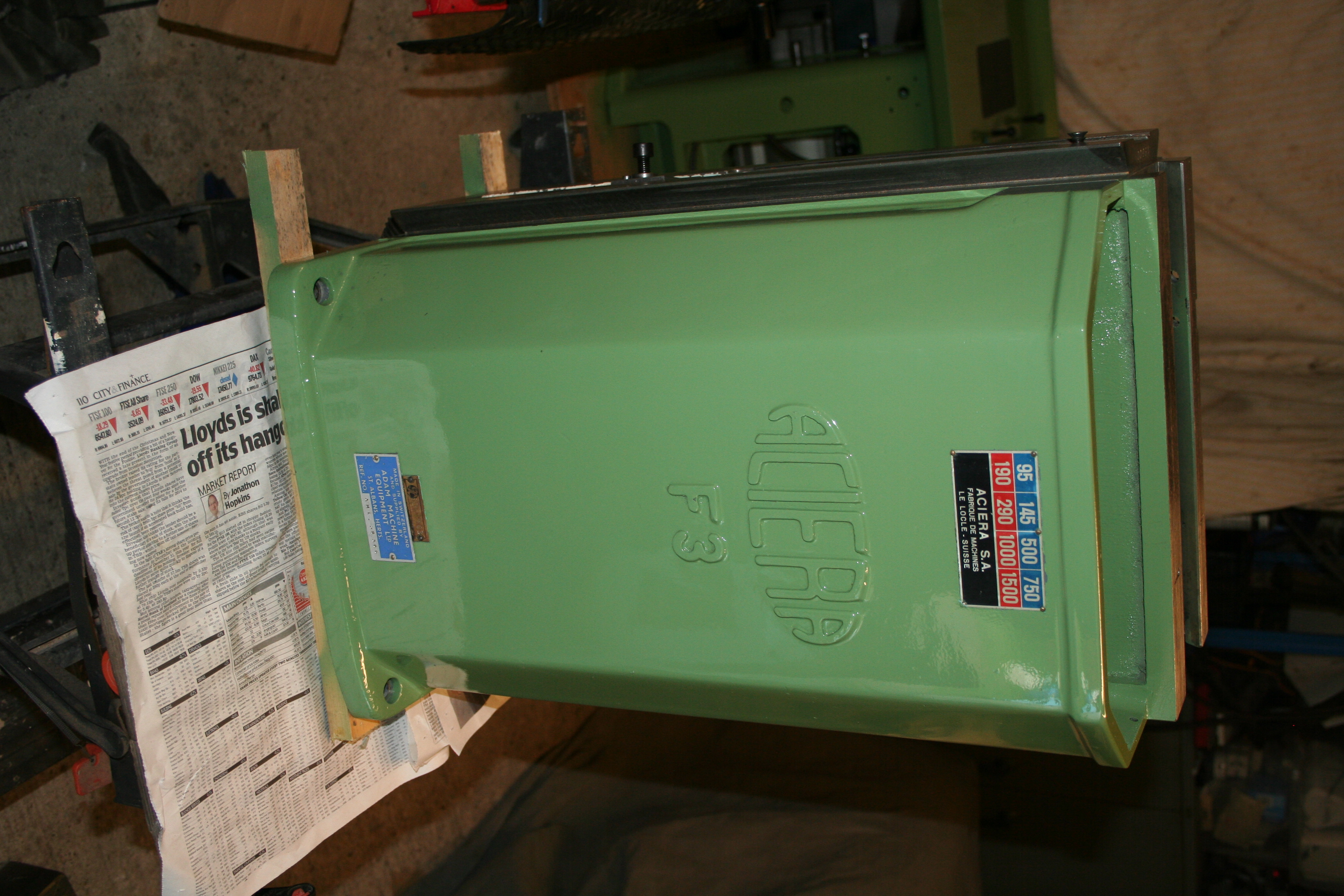
The upper casing is now ready to fit to the base – just need to grease the bearings! The casting overhangs the bench so that I can easily get to the nut at the end of the z-axis screw.

Now, here is a question: How do you get the ACIERA & F3 characters to be highlighted in black – easily?IMG_0661 IMG_0663

Z-Axis etc

Its slow progress at the moment. The weather has been cold and SWMBO dictated that some household DIY was in dire need of doing.

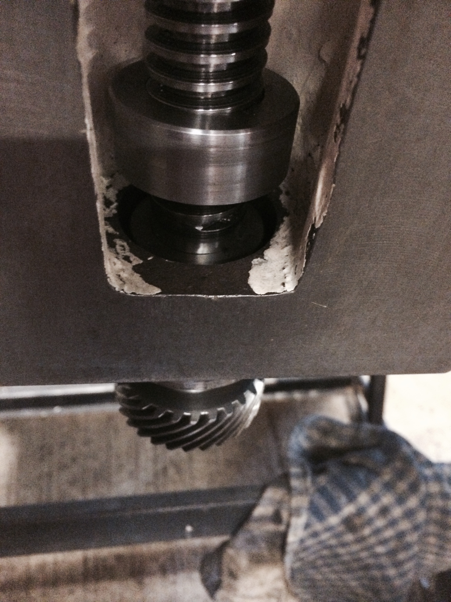
It’s a good job I took a couple of photos of certain items when I dismantled the machine. I was a little puzzled by the lower gear on the z-axis as the gear could fit either way round. (Mind you it may be useable the other way round when it gets more worn!).

z-axis bottom gear

This particular shot shows the completed unit (put back the same was before dismantling). Most diagrams I have looked at show a locking nut (i.e. 2 in total) but there was never one fitted and no room for one unless half nuts were fitted. To be safe, I fitted a shake proof washer for good measure. Then I reversed the dismantling procedure using the air impact wrench to tighten up. The upper cap has a O-ring that makes it a little tricky to move down the main screw. So it had to be rotated most of the way. Then a gentle tap to located it in position above the upper thrust bearing.

z-axis above lower nut


I’m waiting for the new bearings for the coolant pump and once that is fitted, I can then fit the drip tray and crack on!