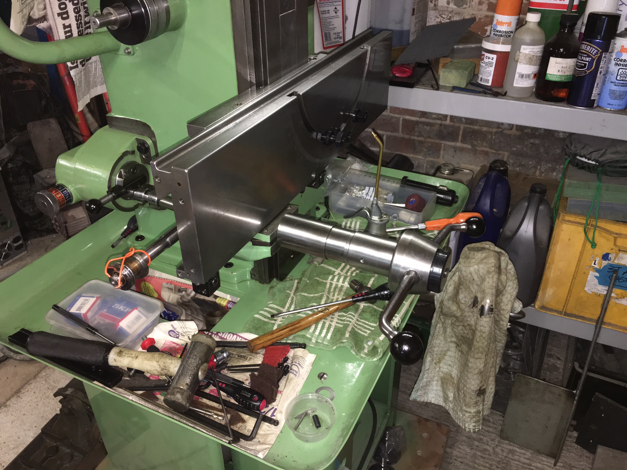
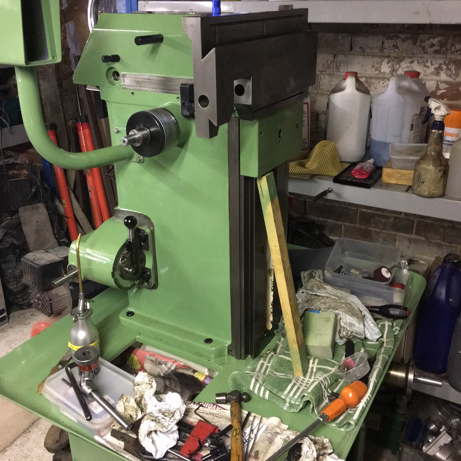
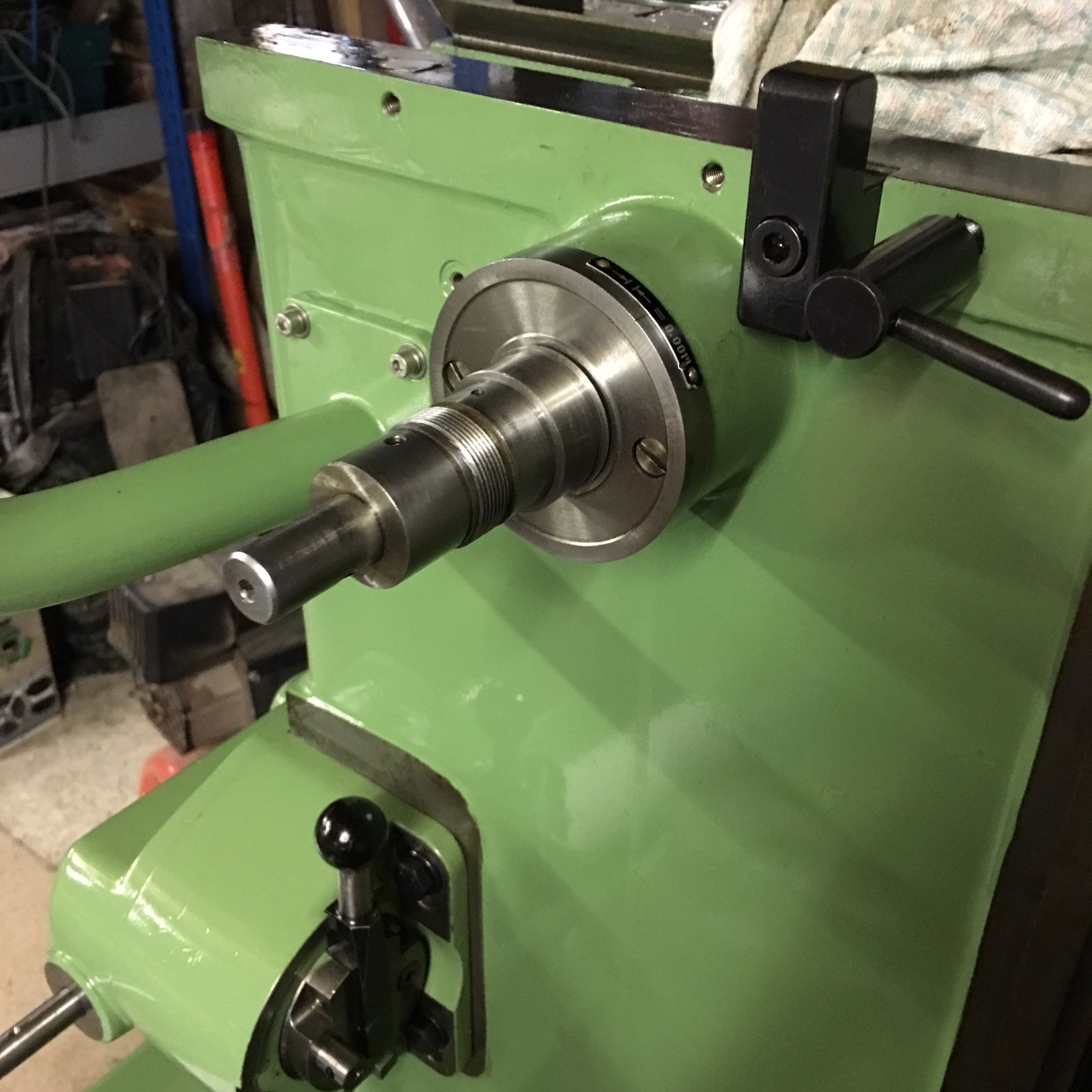
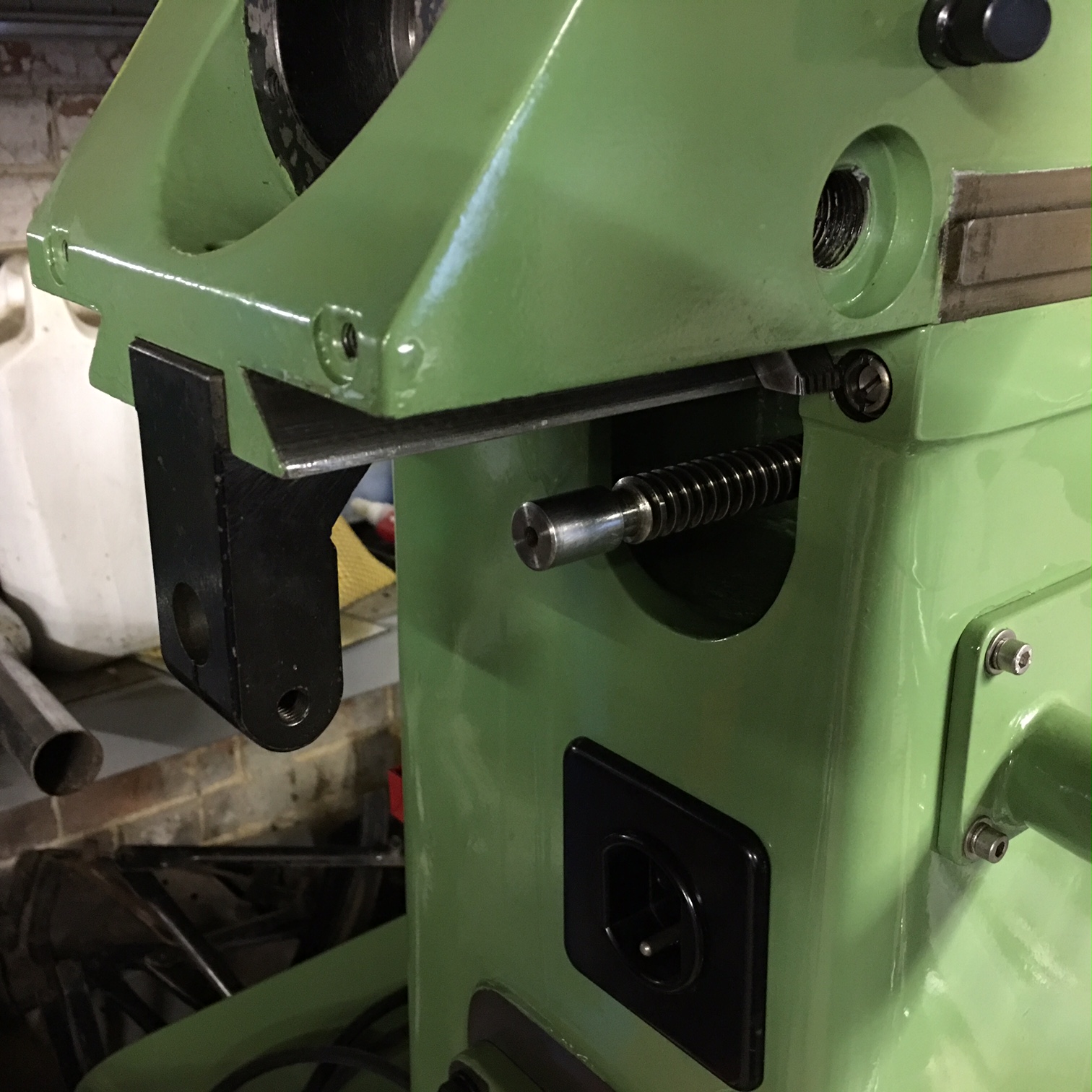
Slow progress!

I have been busy building a new shop for the F3 mill and it has taken a lot longer than anticipated – together with the fact that the house is now on the market, its a busy time.

Anyway, I hope to purchase the DRO in the next few weeks and have that installed before Christmas…….


Gearbox problem!

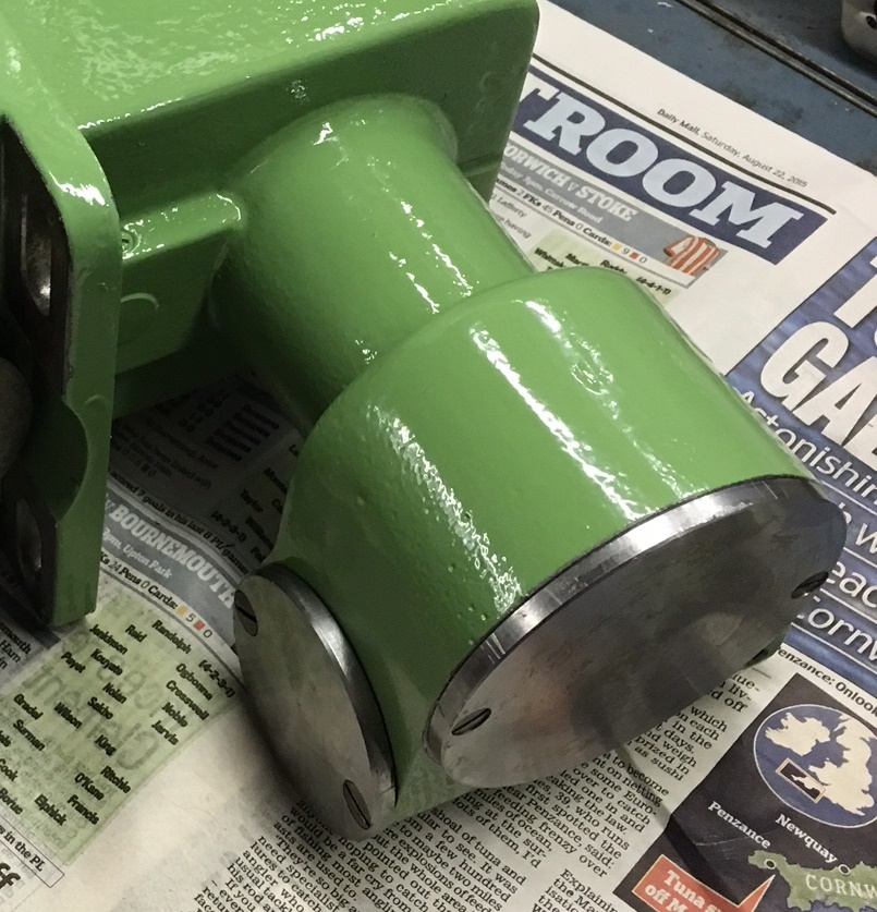
I’m not sure what happens here but after fitting the geabox, I seemed to lose drive to the apron. So I removed the prevoiously fitted pulley and removed the unit. By taking off the round cover plate (the larger one in the foreground) it is possible to push back the rack that the speed selector acts upon. It is in the centre of the gear when you remove the plate. Voila, the gearbox then works again. I think this all came about when I removed the selector dial.

IMG_2667 - Copy

My only issue now is that when I removed the pulley, it shot off the shaft, hit the casing and landed on the motor and you guessed it, it chipped a lump out of the edge. I will braze this all back up and turn up on the lathe. Looking at the chip, it has rust in the broken area and it looks like I dealt the final blow to it breaking off. Photos to follow when I get a moment.

This is the view from the top inside the belt ‘well’ – pulley removed.

IMG_2741

Apron slide graduated wheel

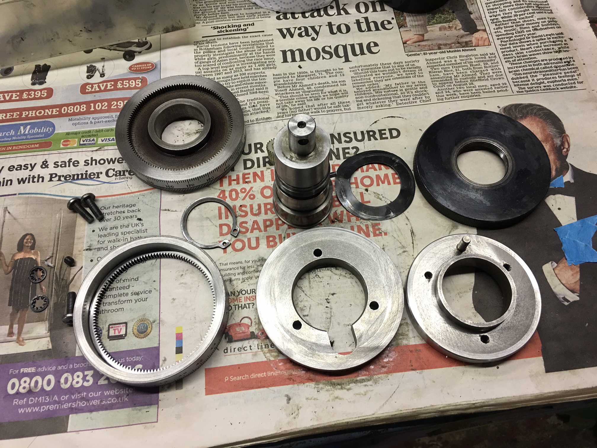
Below, you see one of the twin dials on each of the axes. It seems unecessarily complicated but I suppose there is some good reason the Swiss made it this way! The picture show all the parts except the nylon gear that is hiding behind the screw extension on the left.

IMG_2737

Below, you see the extension fitted to the screw. This is fitted in place with a roll pin – the hole shown ready for the pin to be driven in.

IMG_2738

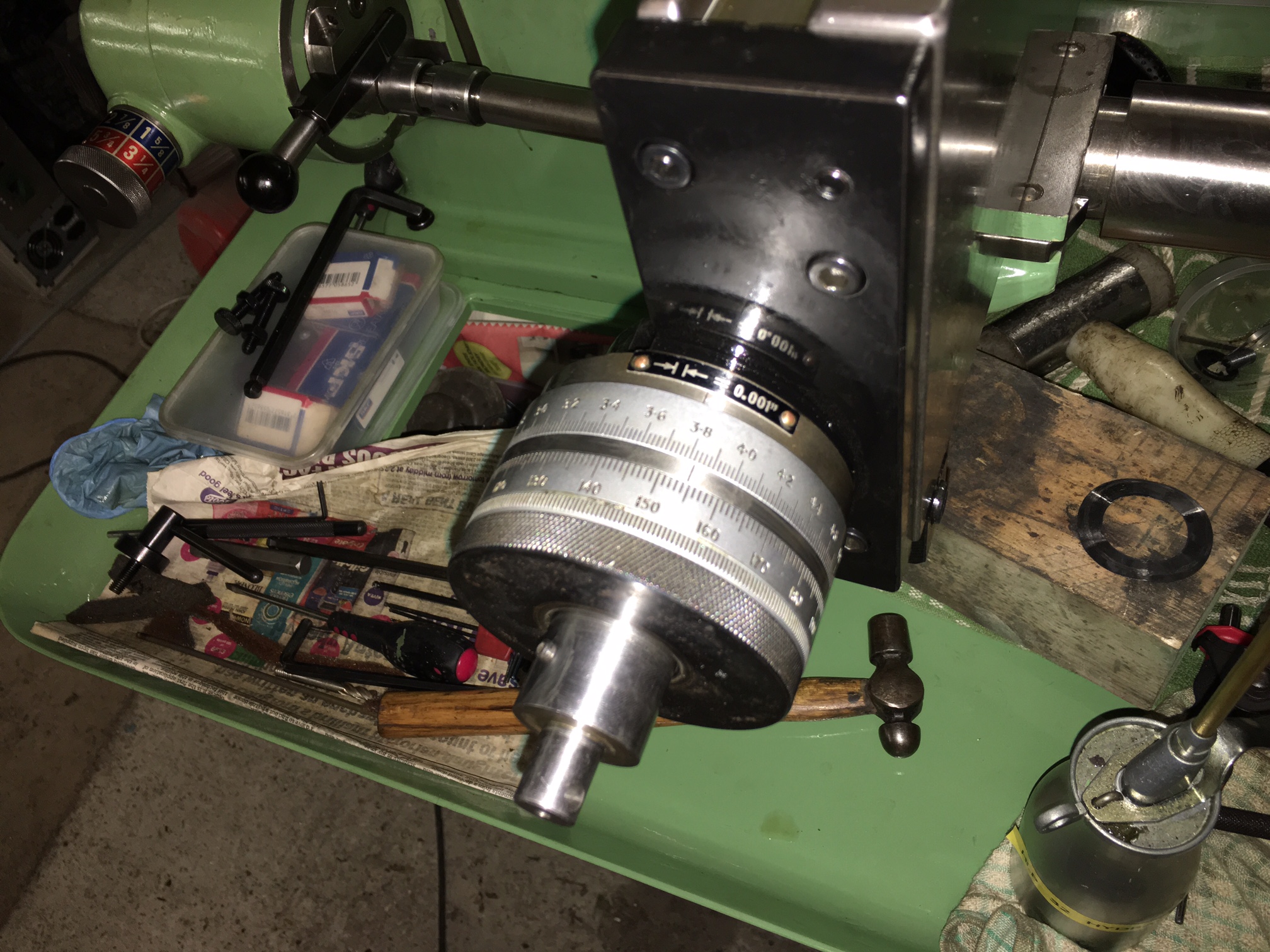
The photo below shows the twin dials fitted.

IMG_2739

Don’t you just hate it when…..

….you find a bit left over in the box! To be more precise, you find a part you are not sure about.

IMG_2734

The part in question is item ’20’ in the above diagram and is fitted to keyway in the screw for the apron slide. I’m not sure of its purpose (I will investigate this later) but The bad news was that it was in the box and no in the assembled machine!! So, looking at the diagram, I decided I needed to drop the rapid traverse unit (removing the 4 bolts) remove the two end caps of the apron and then I should be able to remove the screw to insert this ‘slider’.

IMG_2736

Of course, the nut needed to be removed again (above) and then the screw would move out to the right. If you look at the photo below, you will see the screw withdrawn enough to allow the brass ‘spacer’ to be slid down along the bore to line up with the key fixed to the gear. The tang on the brass ‘spacer’ drops in by the gear so it will not slide out.

IMG_2735

It was then a matter of aligning the screw and pushing it all back together. Evertything was bolted back up and it was operational again! Hopefully I will not be taking the apron apart again in the near future.

Rapid traverse fitting

This section should have been described before the fitting of the apron slide!

I have trial fitted the traverse screw and nut together with the gear and bearings. The gear as below.

IMG_2714

For some reason I forgot to photograph the completed gear and bearings. To fit you must fit the bearings into the gap before you try and fit the gear. This is because the casting has two shallow recesses and the whole assembly of bearing and gear is too tight to fit in one go. Once pushed together in the recess, they will stay in place whilst the screw is fitted to the apron. I’m still a little concerned about the play between the slot in the screw and the key which fits in the gear above. (you can just see the round fitting pin for the gear at the right hand end of the gear)

All that was now needed was to bolt up the rapid traverse unit – nothing tricky here, it just gets a little heavy when trying to line up all of the holes for the bolts. I quickly fitted the handles to make sure everything was working OK – and it was!

IMG_2718

I have decided to carry on with the rebuild and I will worry about any wear to the traverse screw and nut later. (and there is a fair amount of wear since cleaning every thing thoroughly) It is not difficult to remove these items to replace them – on the assumption you can even get them!!

It is now starting to look like a complete F3!!

So, what is missing?

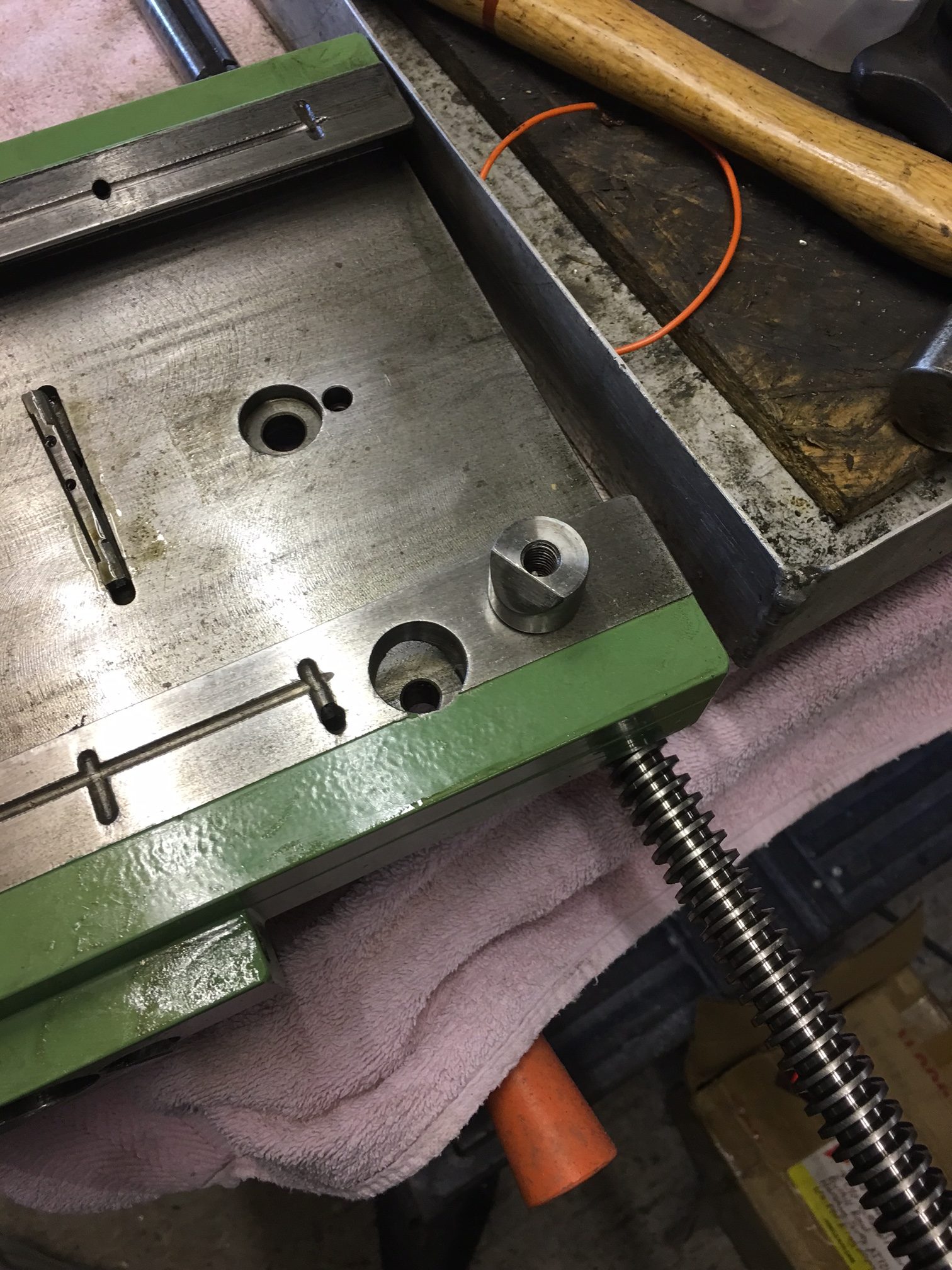
Having fitted the arpon/carriage, I was trying to remember how you locked the carriage vertically. It them dawned on me that it was via this threaded hole on the lower right! And the clamp ring? It was sitting on the bench!!

IMG_2710

So I dismantled it all again and then fitted the clamp and bolt.

IMG_2711

Still, it was a lot easier and quicker this time!

Your carriage awaits!

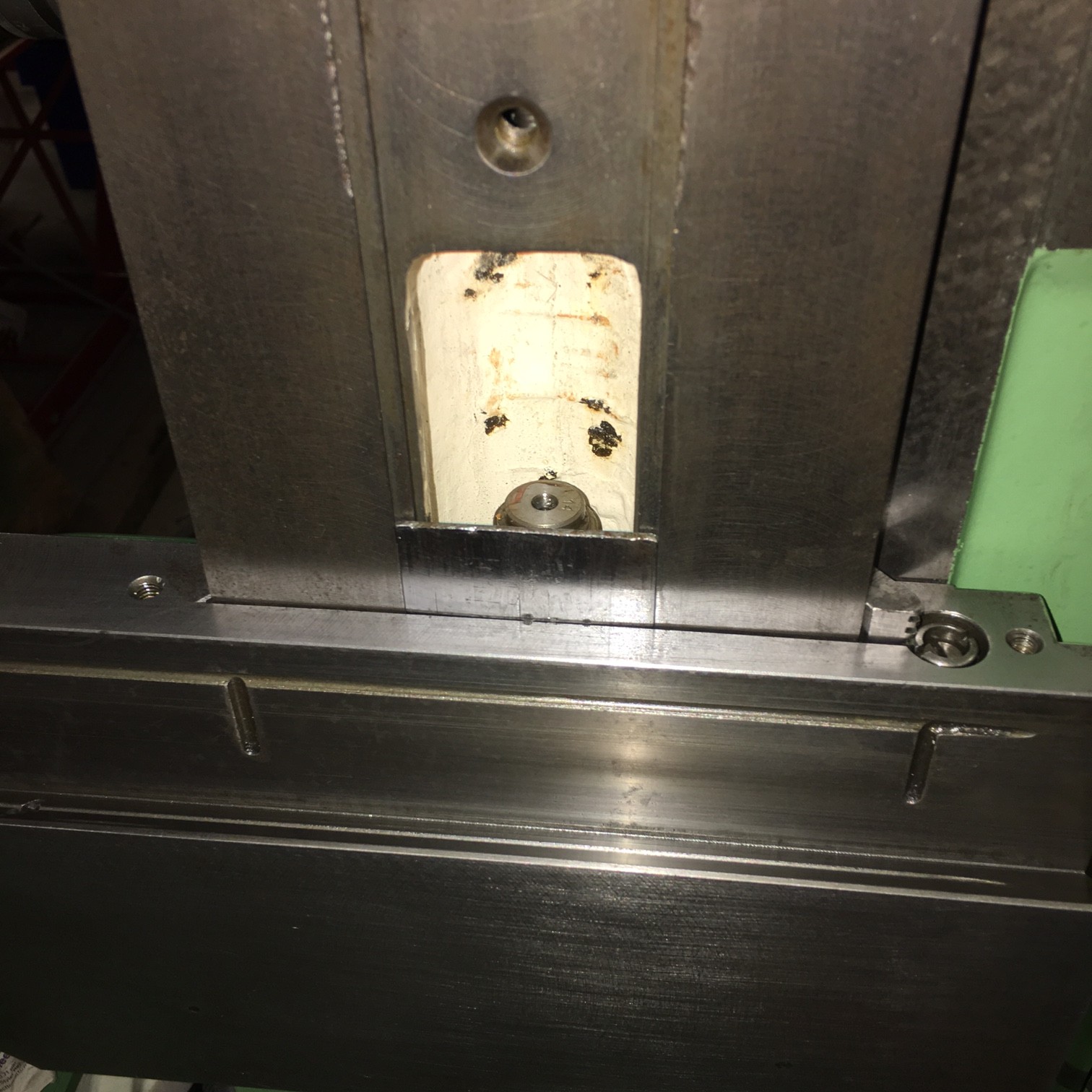
After a little deliberation I decided that to fit the carriage, I would use the column lower blanking plate as a retainer for the ‘scraper & spring’. This is the thin plate in the centre of the photo below. I then left the nut loose on the top of the main vertical screw and fitted the carriage with the jib loose.

IMG_2693

It was then posssible to lift the carriage without worrying about the scraper falling out whilst I positioned the nut in line with the cap head retaining screw. It was a relatively straighforward proceedure. All that was then required was to engage the screw with the nut and then do some initial adjustments. Below is the point where, with decent light, yu can align the saddle with the nut. Once in view it is easily aligned to fit the socket head bolt.


IMG_2712

Below is the assembled carriage.

IMG_2692

I then put the vertical head on the machine – mainly to get it out of the way!!

IMG_2698

When I was masking up I wan’t sure if the edge of the vertical head was painted. I can now see it was but I shall leave it as is.

IMG_2699

The next stage will be to clean up the slide apron and then refit.

Z carriage

After fitting the horizontal head, I decided the main carriage should be fitted. What I did was to lift the carriage onto the column and steady with piece of wood as shown below. The jib adjuster was then fitted and adjusted to take up most play but still allow me to easily slide the carriage up and down.

IMG_2685

The wood was just long enough to allow fitting of the piece shown by the serial number as below. It was then possible to lower the carriage 10mm to retain this strip and its corresponding spring. (I have no idea what this strip does. Is it a sort of wiper?

IMG_2688

The problem that then occurs is that you cant fit the carriage over the z screw nut! Removing the jib then allows you to fit the carriage over the nut BUT you then lose the strip and spring. So – a little deliberation is called for and I will return with the answer!

Horizontal section rebuild

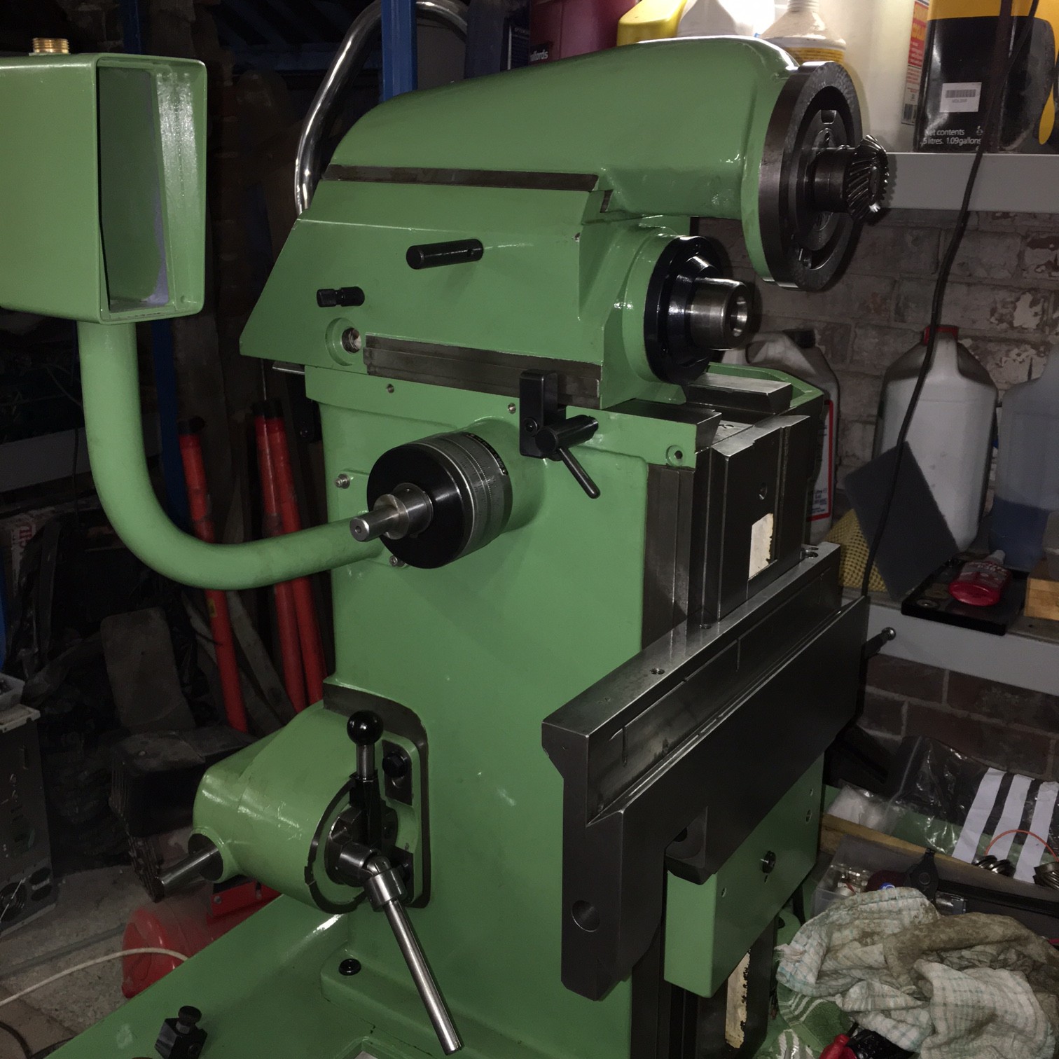
With things starting to come together, it is time to put the main horizontal drive onto the top casting. Of course, having heaved the this drive unit onto the casting I then realised it needed the drive fitting. Fortunately the casting slides far enough forward to allow this. Once this was fitted into place, then the side spindle could be fitted. You will spot from the photo below that I got a bearing shim in the wrong place and this stopped the bevel gear going back far enough to the rear of the machine. The result – the  side spindle would not go in far enough!

IMG_2675

Fitting the side spindle was straightforward once the spindle above was correctly installed,  although most burrs had to be cleaned up a little to allow easy installation into the casting.

The jib piece was fitted and adjusted to take up most play. Once the machine is fully built I will oil and make all the necessary adjustments.

IMG_2669

As you will see, my machine has dual dials – Metric and Imperial – which is a useful addition and one I have not seen before. The dials are mounted on an extension arbor to the main shaft.

IMG_2670

Below is a photograph of the head slid back. The covers will be re-painted black in due course!!
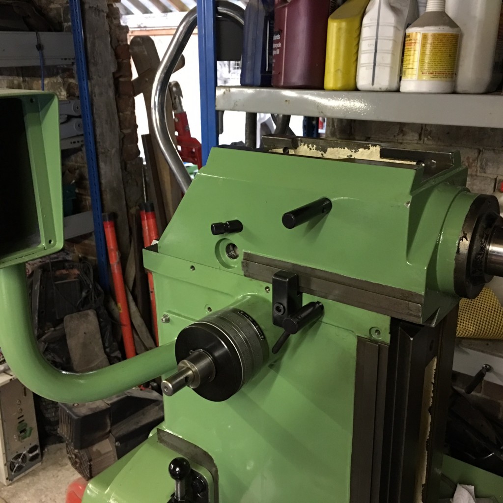
IMG_2671

The head was slid back and the bracket that holds the screw fitted.

IMG_2676