Tilting Table

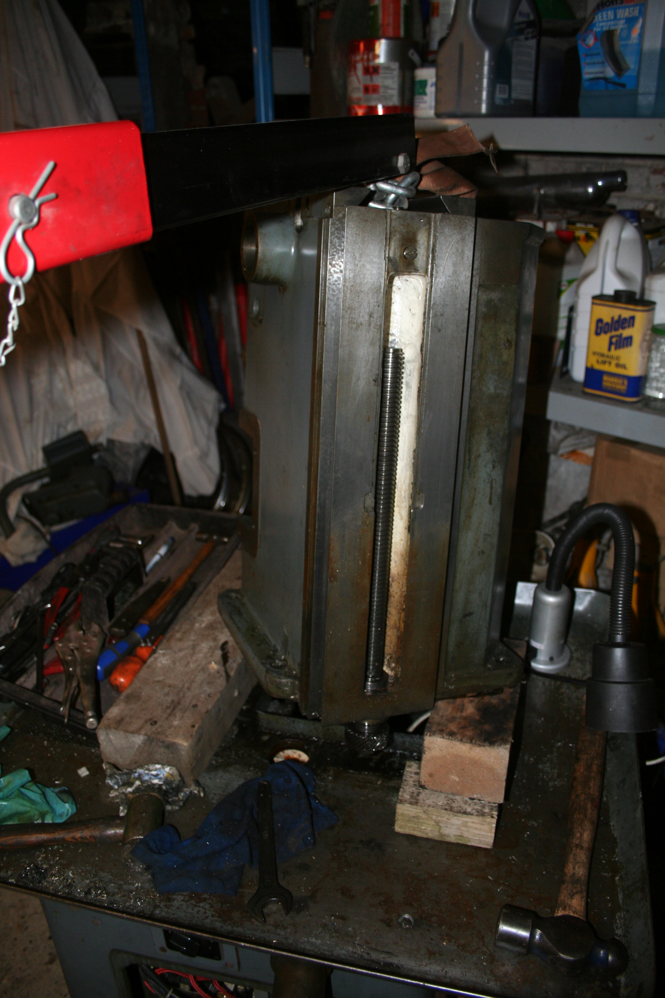
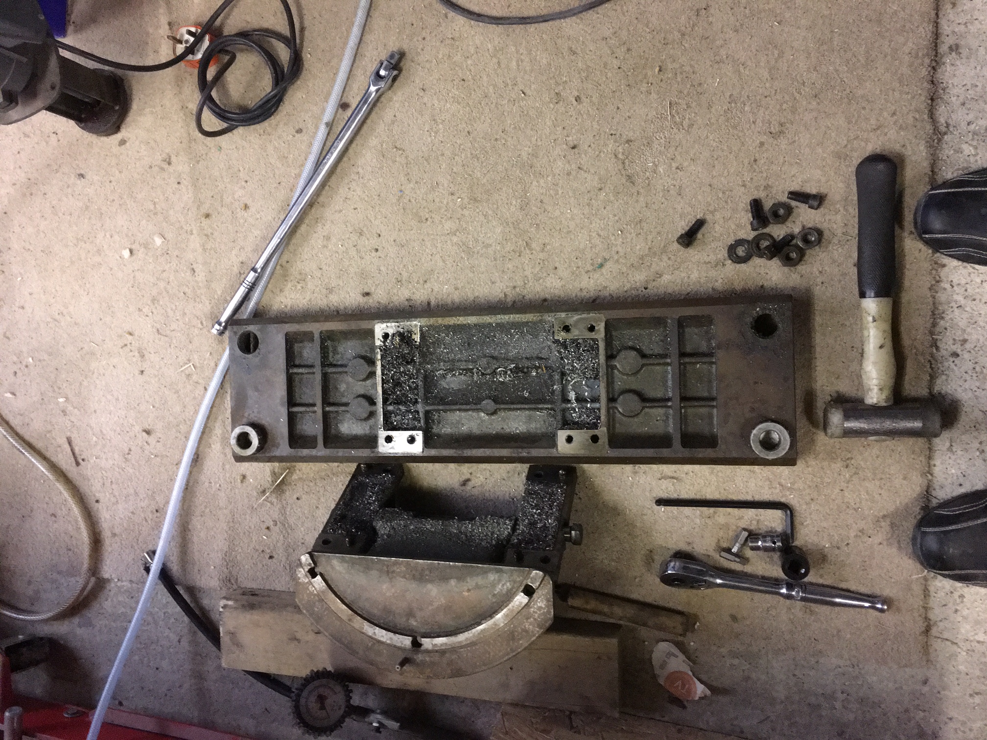
The time has now come to refurbish the tilting table. It is quite dirty and has some marks on it. Disassembly of this is very straight forward.

IMG_2721 IMG_2728

The surface rust on the top is due to my poor storage of the table. The next job is to remove all of the old grime and then clean up. I will decide on which parts require painting in due course.

Dismantling the power feed control unit.

In order to spay certain castings, some ‘modules’ require dismantling. I’m sure it has a better name but I shall call it the power feed control unit!

IMG_1007

The unit was fairly well gummed up and so a strip down was necessary to clean the gears etc. Firstly you need to remove the input shaft. This is held in place with a caphead screw and once removed you can then tap out the drive. I notice the drive pin is made of brass to make sure that it shears before any damage to gears has been done.

IMG_1008

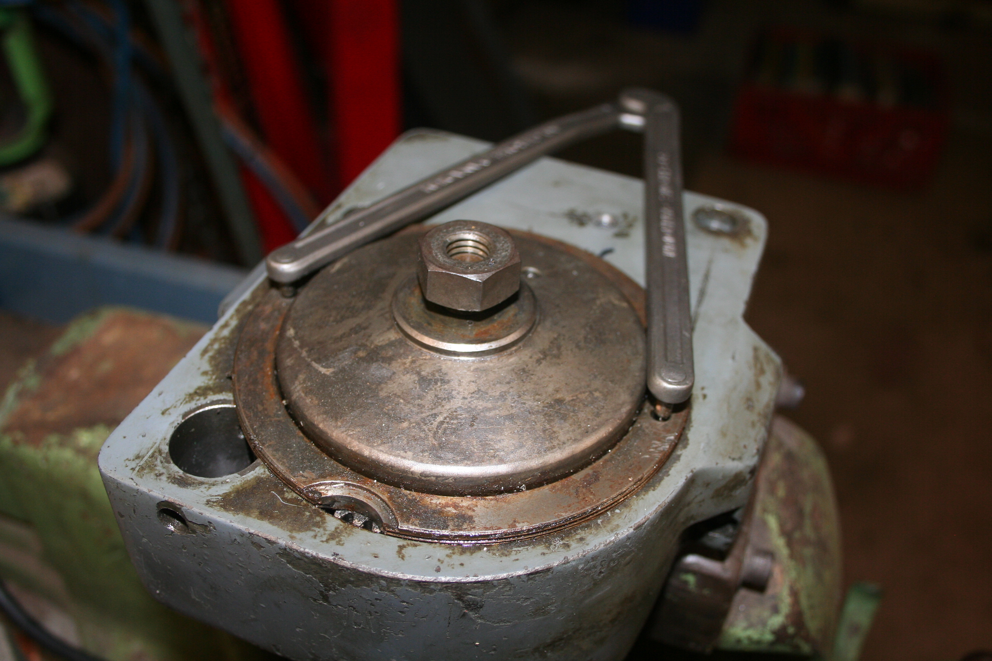
With the aid of a pin wrench, you can then unscrew the backplate. I left the nut loose just in case the spring inside shot items across the workshop – this was not necessary!

IMG_1009

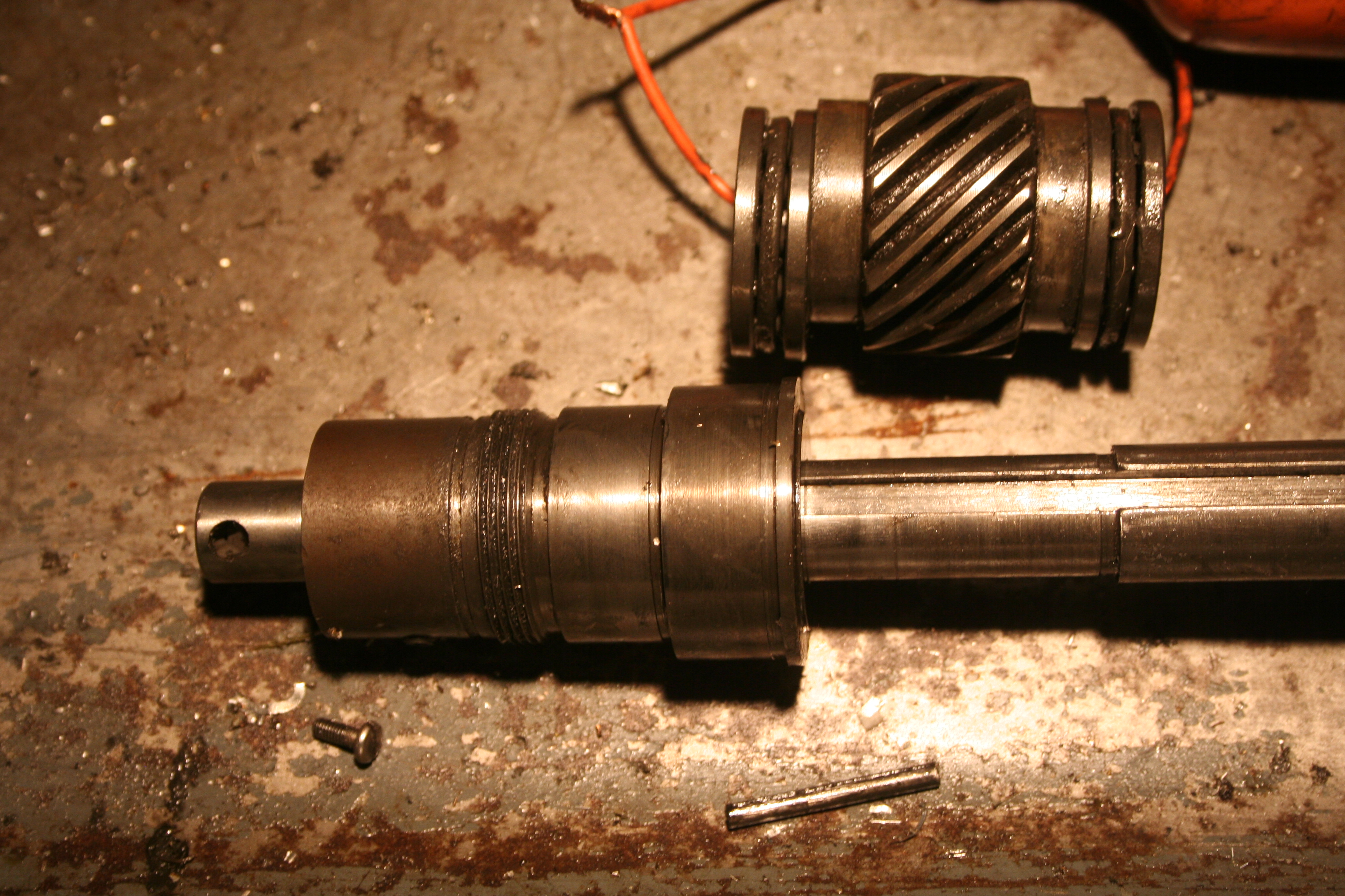
The unit can then be taken apart fully. What I have not shown is the inner nut holding the sliding collars together. This nut was a pig to remove and I ended up using a punch and hammer on one of the pin wrench holes. (a pin wrench had no effect on the nut!). By using the oiling hole on the collar, you can line up this hole with one inside on the shaft. This allows a peg to be inserted to ‘lock’ the unit and thus allow you to try and remove the nut! The last photo show the unit completely dismantled ready to be degreased and a primer coat of etch primer applied.

Fully dismantled!

A concerted effort yesterday enabled me to get the lower casting fully dismantled and I can now concentrate on restoring the mill  – is is sorely needed at the moment!!

Below is the typical use of my puller on the motor pulleys. A spacer (or should I say socket) is used to enable the pulley to withdraw easily over the shaft. Never force the puller!! If it is stuck, look a sharp blow with a hammer on the shaft normally frees it up.

photo2


The motor is easily removed once you can get access to the bolts. Reavealed below is the motor support that is hinged and is removed by 2 very large cap head bolts at the front of the main casting. The upper arm is fairly easy to remove by freeing up the circlips at the outer end and moving the inner ones along the shaft. The whole unit is insultated using rubber / fibre – I assume to protect against vibration.


photo5


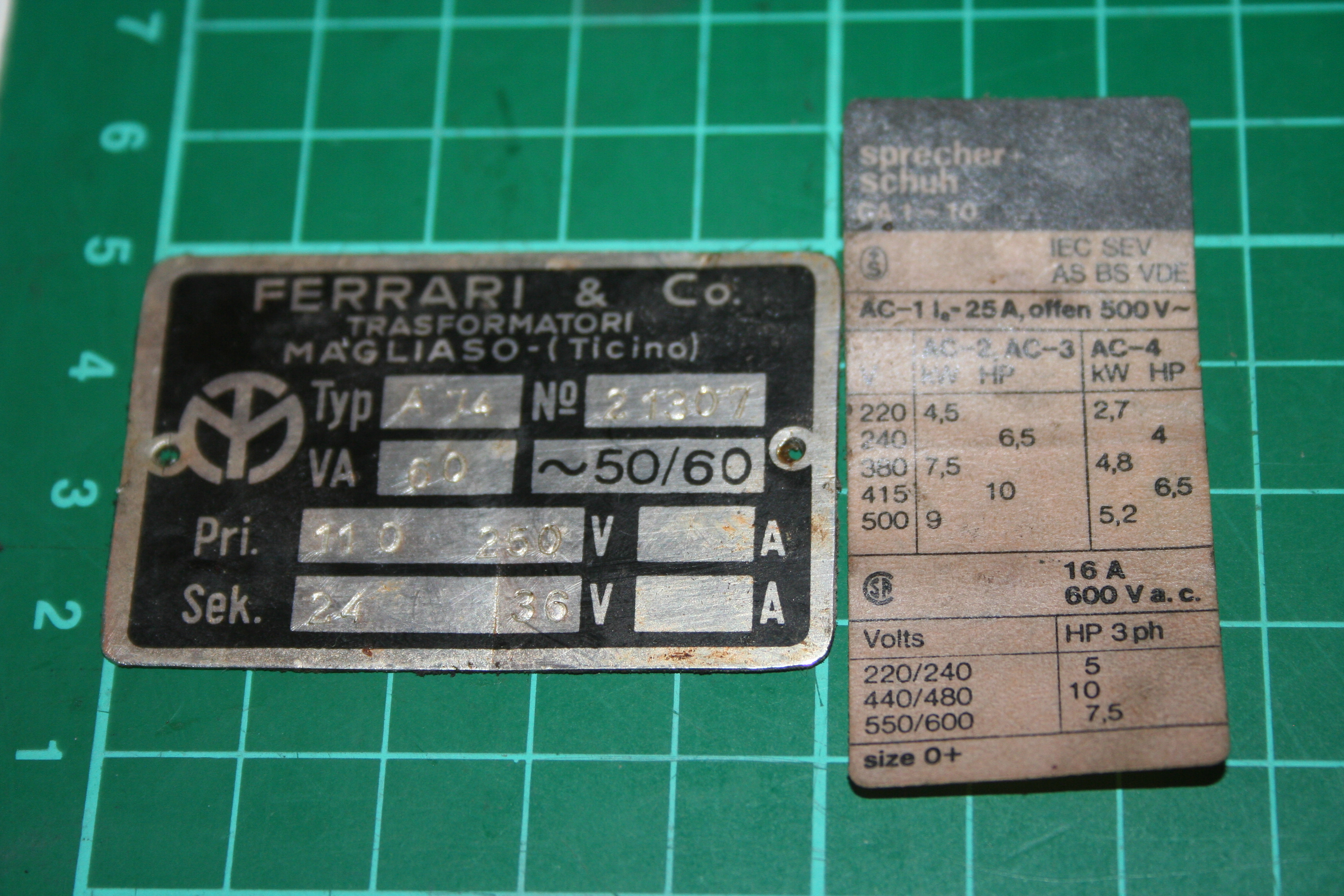
Once the motor was revealed, then the plate below gives the specification of the motor:

photo4

I will use a 220v in to 415v our inverter and replace all of the wiring with appropriate ESTOP and controls using the apertures on the machine.

So, below is the basre lower casting. I now have the task of degreasing all of the componets, cleaning and repainting.

photo3

More work…

Its now the New Year and I’m cracking on with the rebuild. It has been cold but the impetus is on as I have several milling jobs and no mill!! So I’ve got to get on with it!

The first job today was to de-grease rthe drip tray and get that prepped ready for painting.

IMG_0427


It came up fairly well. A final degrease / rust treat and then 2 pack paint will be applied.

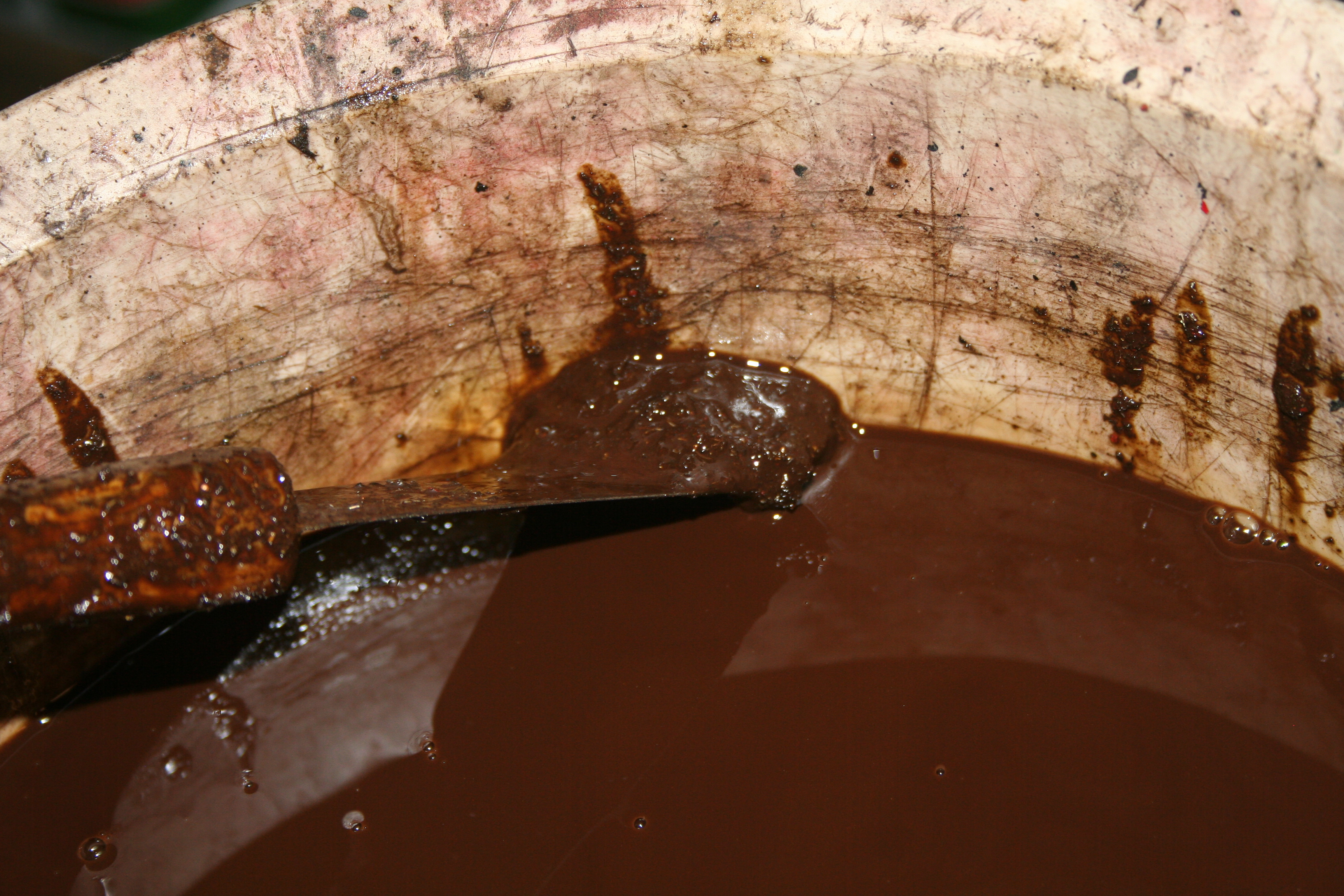
The next job was to clean out the coolant resevoir. This was truly an awful job and its not quite finished yet. You can see below that this is sort of sludge I had to get rid of.

IMG_0425

I’d say there was al least 2 litres of this stuff! The plus side was that whilst cleaning, a lock screw was revealed that holds the pump into the lower casting. (the photo is very poor but gives you an idea- I’ll redo it next time)

IMG_0424

A final clean is now required, the pump pulley removed and then I’ll move onto the motor. Whilst removing the panel at the front I noticed that there was a collection of screws and plates in the bottom of the casting (a sort of trap) There here for reference really but I’m not sure they are relevant (yet)IMG_0430

Almost dismantled!

Last night I lifted the upper casting higher so I could get an air impact wrench on the lower nut. It was undone in half a second and I didn’t even need to hold the z-axis screw with anything. (I’ll use the same technique for tightening up!) It was then a simple matter of removing the bearings and collar (using a pin wrench) and lifting the whole unit away from the casting. I made a careful note of the order in which the bearings etc came off and reassembled them onto the screw for cleaning later on.

IMG_0411

The upper casting is now bare (except for a few oil nipples) and is ready for a good clean as does the drip tray.

The lower casting oil well is half full of swarf and oil and will need some heavy duty cleaning.

IMG_0408


The Y-Axis screw is within a large collar that is mounted into the lower casting at an angle. There are 2 large grub screws that hold this in place. Well, only the lower one on my F3. Even removing the grub screw it seemed pretty much stuck. Some gentle persuasion with a wooden block and hammer got it shifted.


IMG_0409


All that now remains to be done is:

  1. Remove motor and fittings
  2. Remove electrics and cables
  3. Remove coolant pump

IMG_0410

Once the above has been done, I can move on to the next section of cleaning, inspection and refurbishing before the re-assembly.

Lift-off & Motor?

A little warmer this evening!

OK, I’m now ready to remove the top main column from the base & tray. I just need to get the hoist in position. I also have no idea where to sling the ropes!

IMG_0398

IMG_0402

Its far too cold to get on my hands and knees to attempt to remove the motor but a quick look has me puzzled – what is the best way to do this?


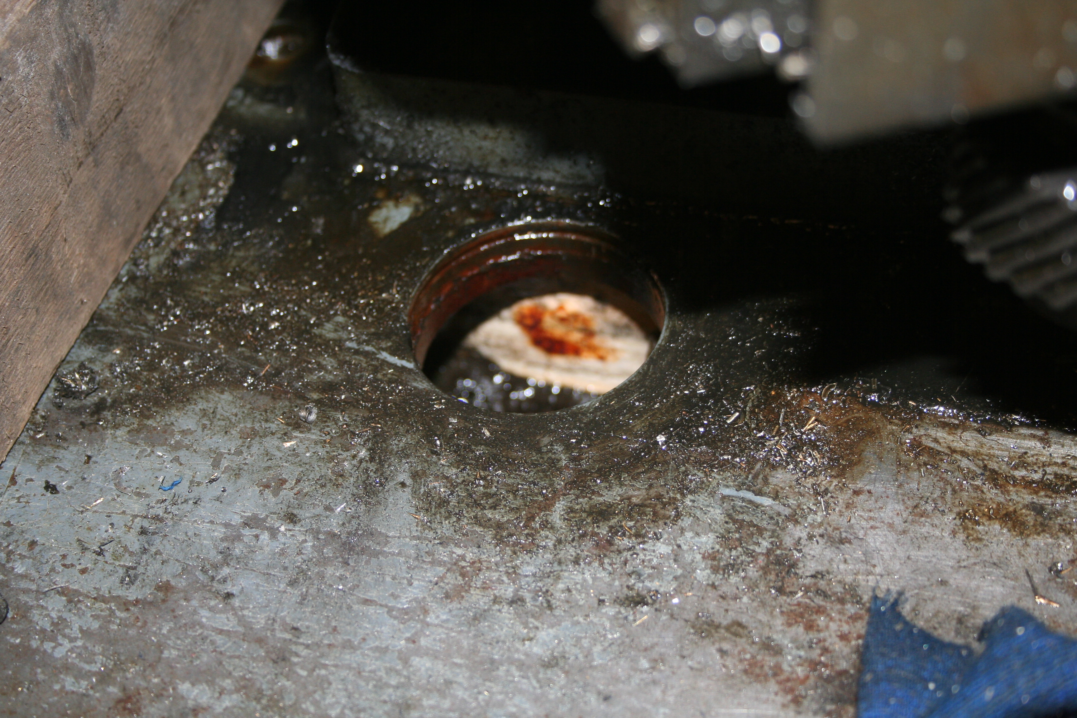
With the hoist in place I gingerly raised the main casting! What appeared to be happening was that the boss for the z-axis spindle was rusted to the drip tray.  IMG_0401

It took a little while to work this out as the tray seemed well fixed at this point. Anyway a block and a sharp knock and the drip tray dropped clear. Above is the rusty crud around the hole holding it all together.

So, how do I now remove the nut at the bottom of the screw?

IMG_0399

Further dismantling


So below is the photo after removing the z-axis carriage.IMG_0388

Last night saw the removal of the auto-feed gearbox. This should have been a simple operation but necessitated me removing the pulley from the shaft – and of course, it didn’t want to budge. Now under normal circumstances it would be easy to put on a puller and then just ease the pulley of its keyed shaft. However, there is no room in the belt ‘cavity’ and so I ended up using wedges behind it. After a little encouragement it moved and I was then able to remove the gearbox with a little turning and twisting (its quite a close fit!).

Thr cables have been now removed from the light & start/stop pod and the arm removed.

Here are a few more photos:

IMG_0395 IMG_0394

I’m not sure yet how the top casting (main body) comes away from the base/drip tray. So for nothing better to do,  I removed the z-axis nut.

IMG_0393

So, tonight’s teaser – what the heck is this screw for?:

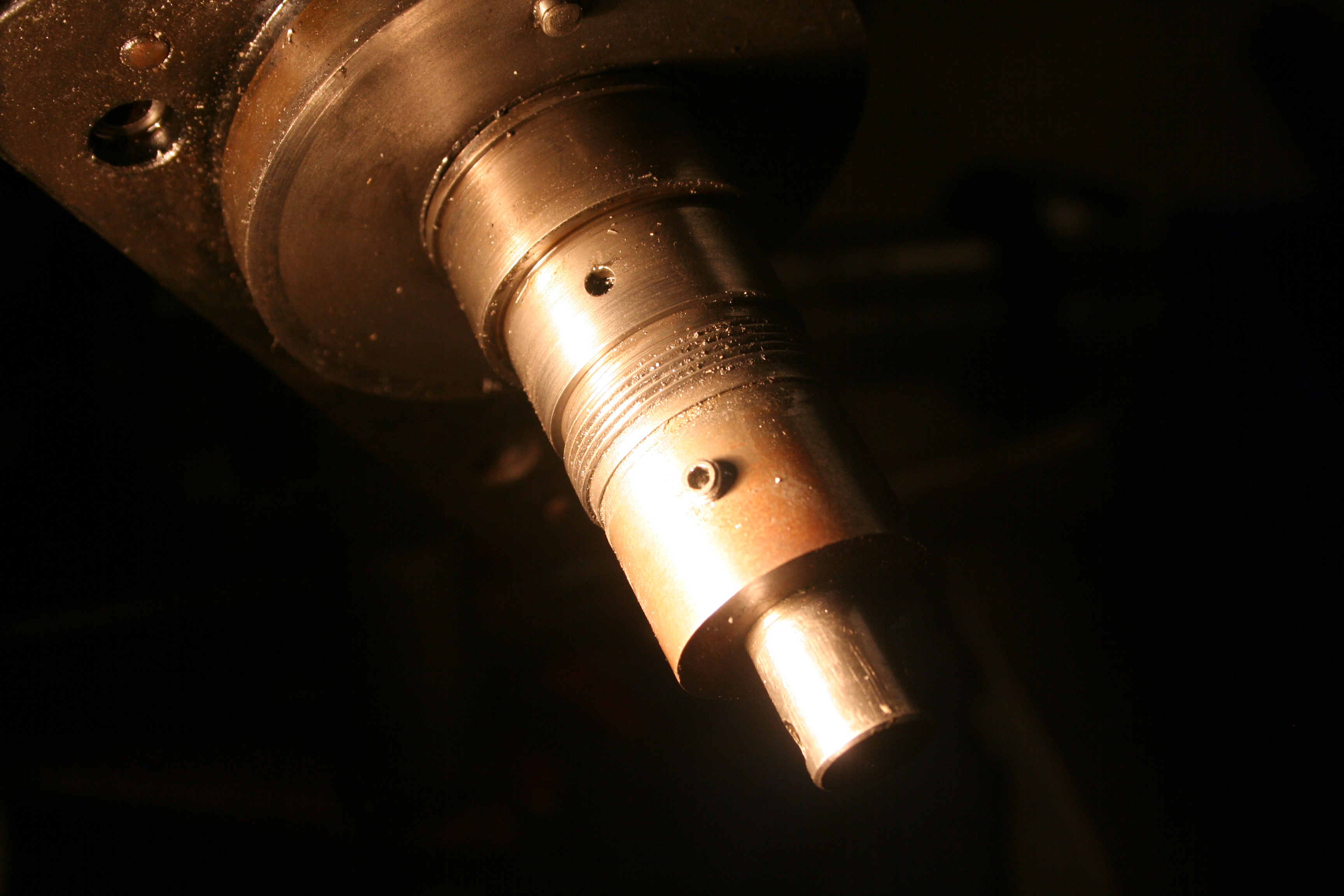
IMG_0396

I  really can’t see what purpose it serves!


Your carriage awaits!

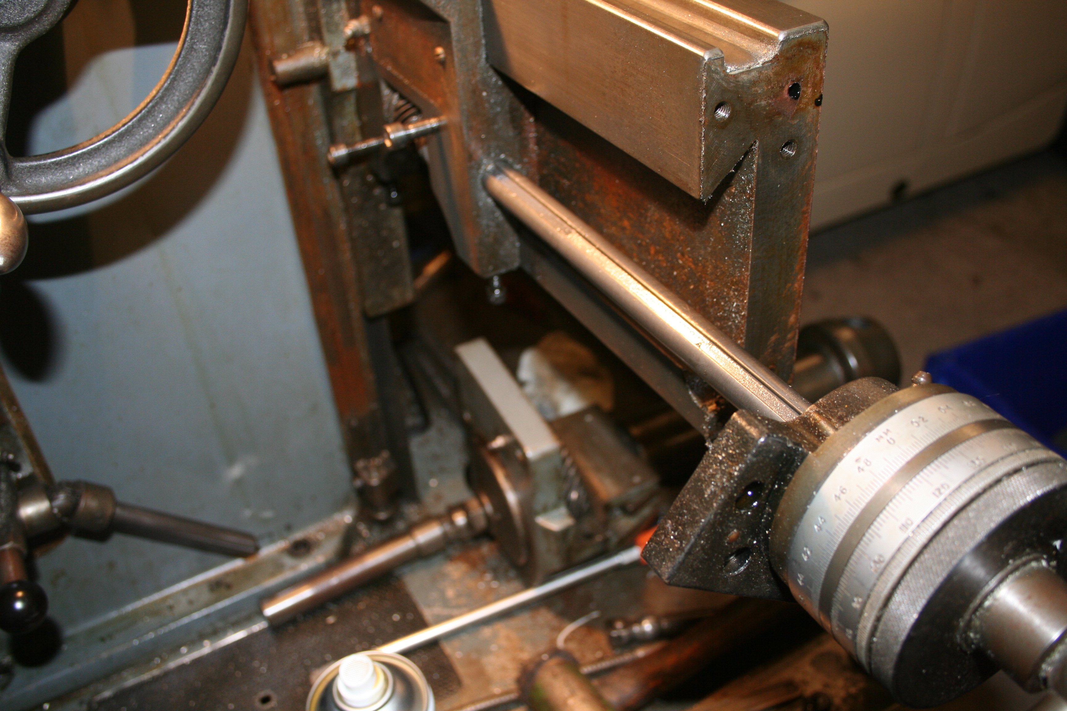
After a little thought, I established that there was a collar on the end of the screw – something made to allow the dual dials to work. This covered over the original thread of the screw that is used on single dials. With the pin drifted out and the grub screw loosened, then the collar just came away with a gentle tap.

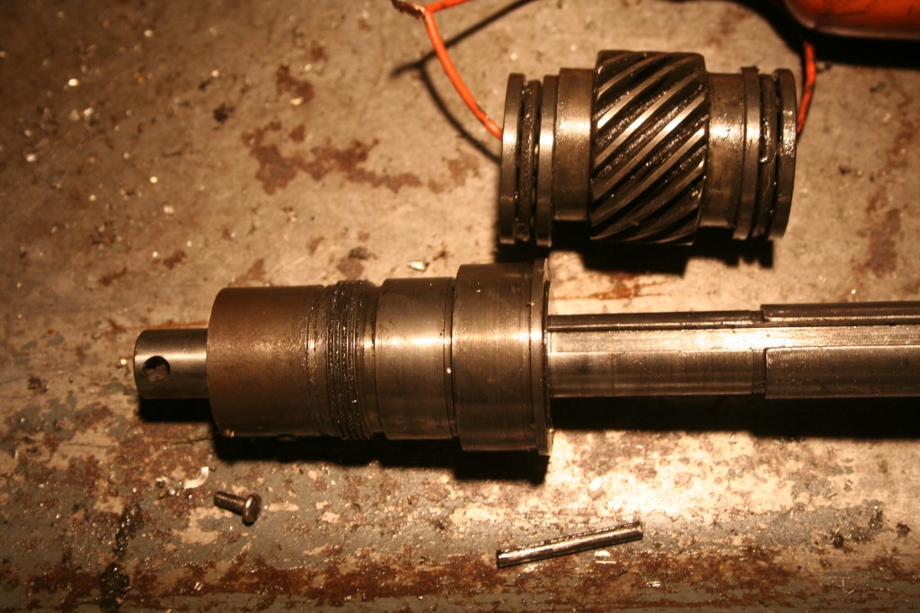
IMG_0384


IMG_0385

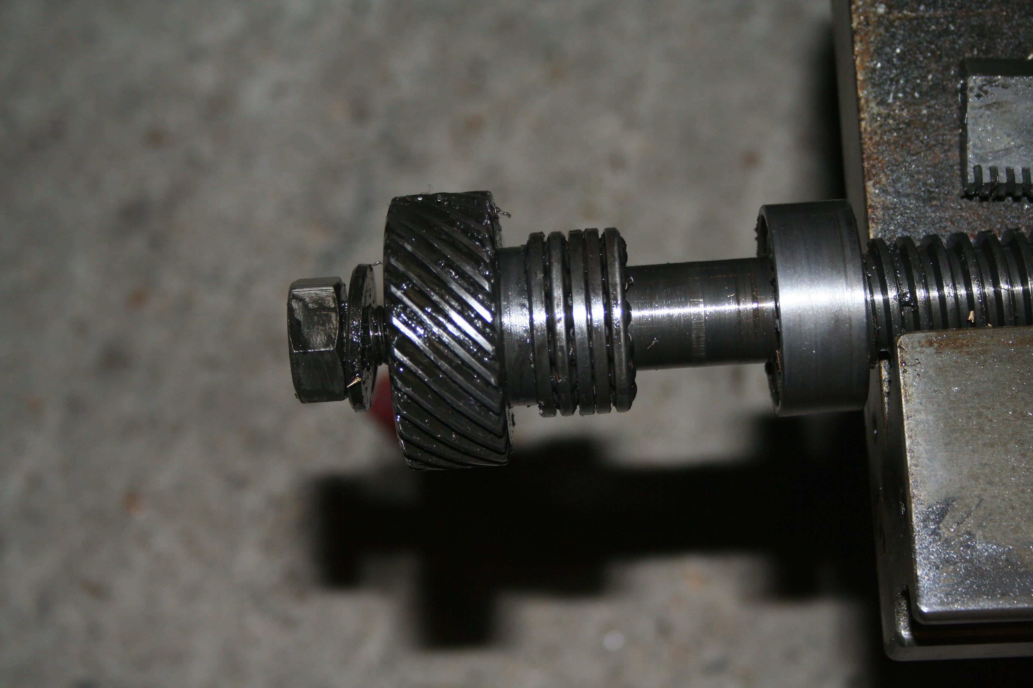
The screw was then pulled out of the carriage towards the opposite end. I held my hand under the gear in the carriage for fear it would fall away but the grease and dirt held it all in place. What I didn’t spot was how the bronze key (a 2nd key next to the one pinned to the helical gear) was held in place – probably retained in the gear / bearing cluster. I’m sure it will all become clear on the re-assembly!

IMG_0382

Next, we move onto the Z-axis. From what I can see, I just need to remove the carriage from the z-axis nut, remove the jib strip and it should lift off. And indeed, that is what was required. The nut needed to be moved ‘back’. To do this, I removed the central cap head screw and then put it back a few turns and gently tapped it. This moved it away from the nut and the cap head screw stopped it falling to the drip tray. All I needed to do was to lift the carriage up off the machine.

Next item to remove was the top dials for the Y axis – easy now I know!

IMG_0387

Well, the roll pin on this one is buggered! So that can wait.

My next task was to remove the auto traverse gearbox….

IMG_0386

This will need a little thought! As removing the bolts does not allow it to come away from the main casting! – the pulley is in the way, I think.
A little progress!

I have now managed to remove the carriage. Quite simple with the other endplate onbolted.

IMG_0376

It is now possible to just slide off the carriage in the opposite direction.

IMG_0377


And voila, the carriage is now off the machine.IMG_0378

OK, with that done, I now need to withdraw the main screw. Whilst deliberating why the screw will not come out, I decided to remove the dials etc. All straight forward up to this point:

IMG_0379

So, looking at my exploded diagram, I’m none the wiser. My main screw has a keyway along part of its length and the keyway insert seems to be stopping the screw coming away from the body and helical gear.

IMG_0380I’m also wondering if this ‘pin’ is stopping things. More deliberation and wine, I think!