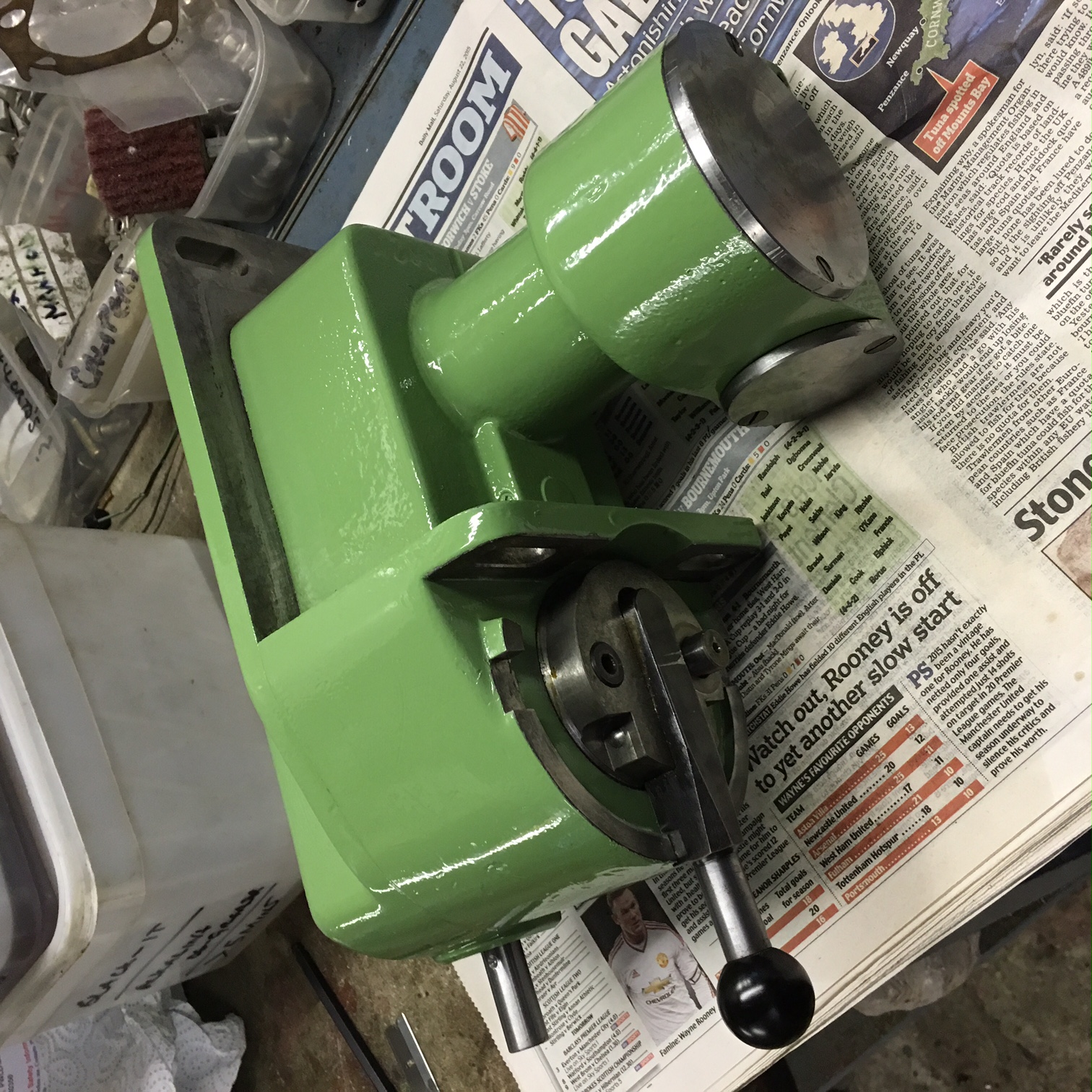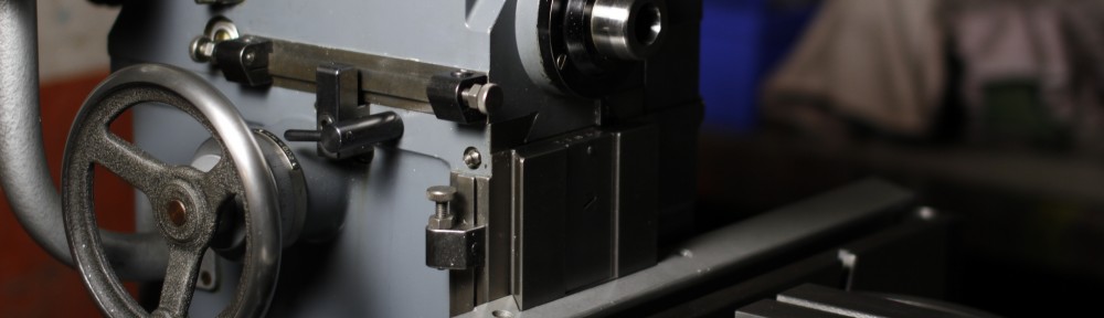
Apron slide – cleaning up the tarnish.

Most of the light tarnish on the smaller items is removed on a bench grinder fitted with a bundle of fine scotchbrite discs. However I have tried by hand to do the larger parts and it is soul destroying. I use a fine pad that does not affect the metal. I have tried a few experiments but the one below seems to take the some of the effort out of it.

IMG_2697

The above it is an air mini orbital sander.  To the velcro pad I attach a 50mm disc of scotchbrite and use this with oil to gradually clean up the metal. The pad seems to stick well to the velco – more by luck than judgement! As you will see below, ask the metal is starting to clean up well and when finished should look good.

IMG_2696

This process will also be applied to the tilting table.

After a good going over with the ‘air brush’ I will give it a final hand polish with an ultra fine scotchbrite pad. The results so far are not bad!

IMG_2705


Your carriage awaits!

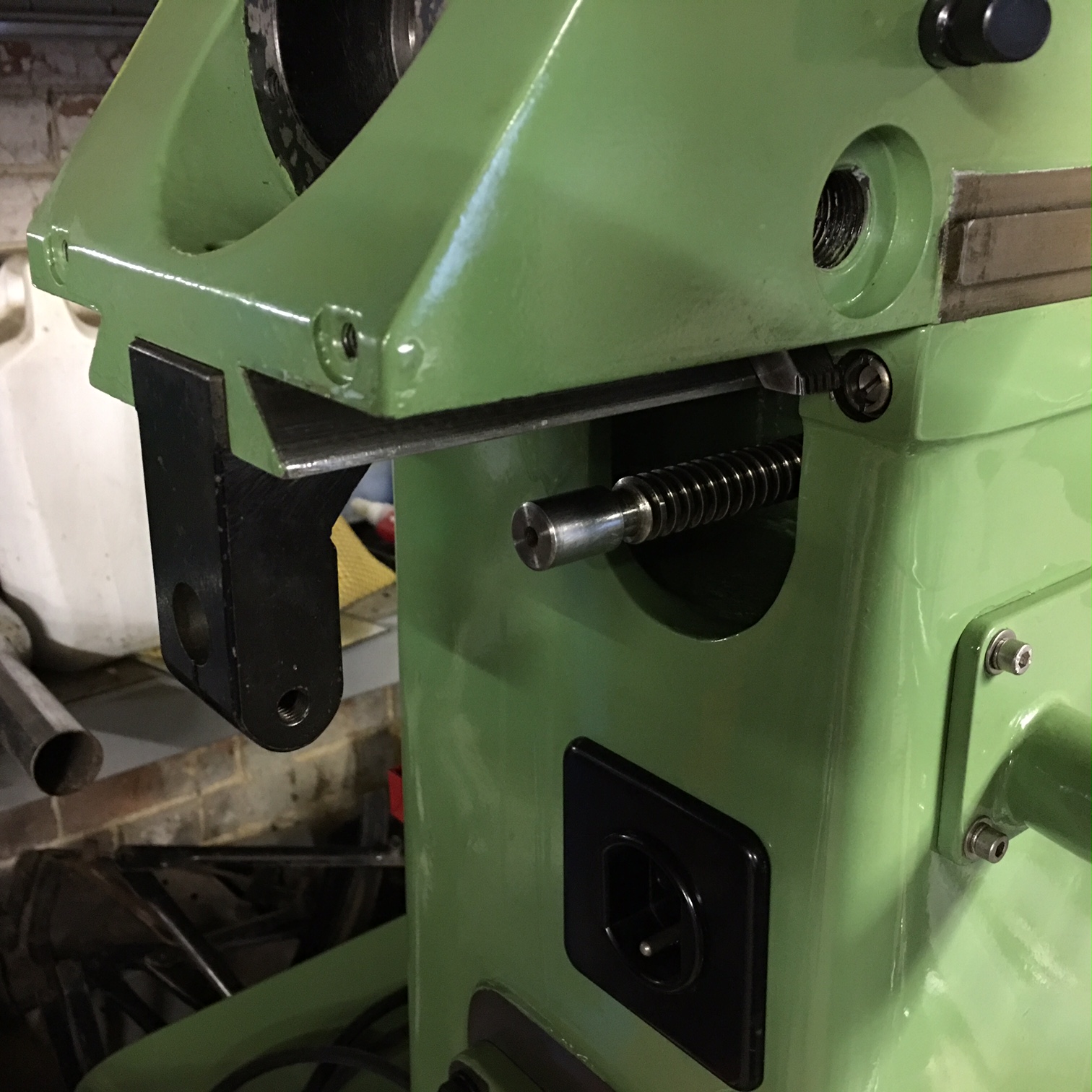
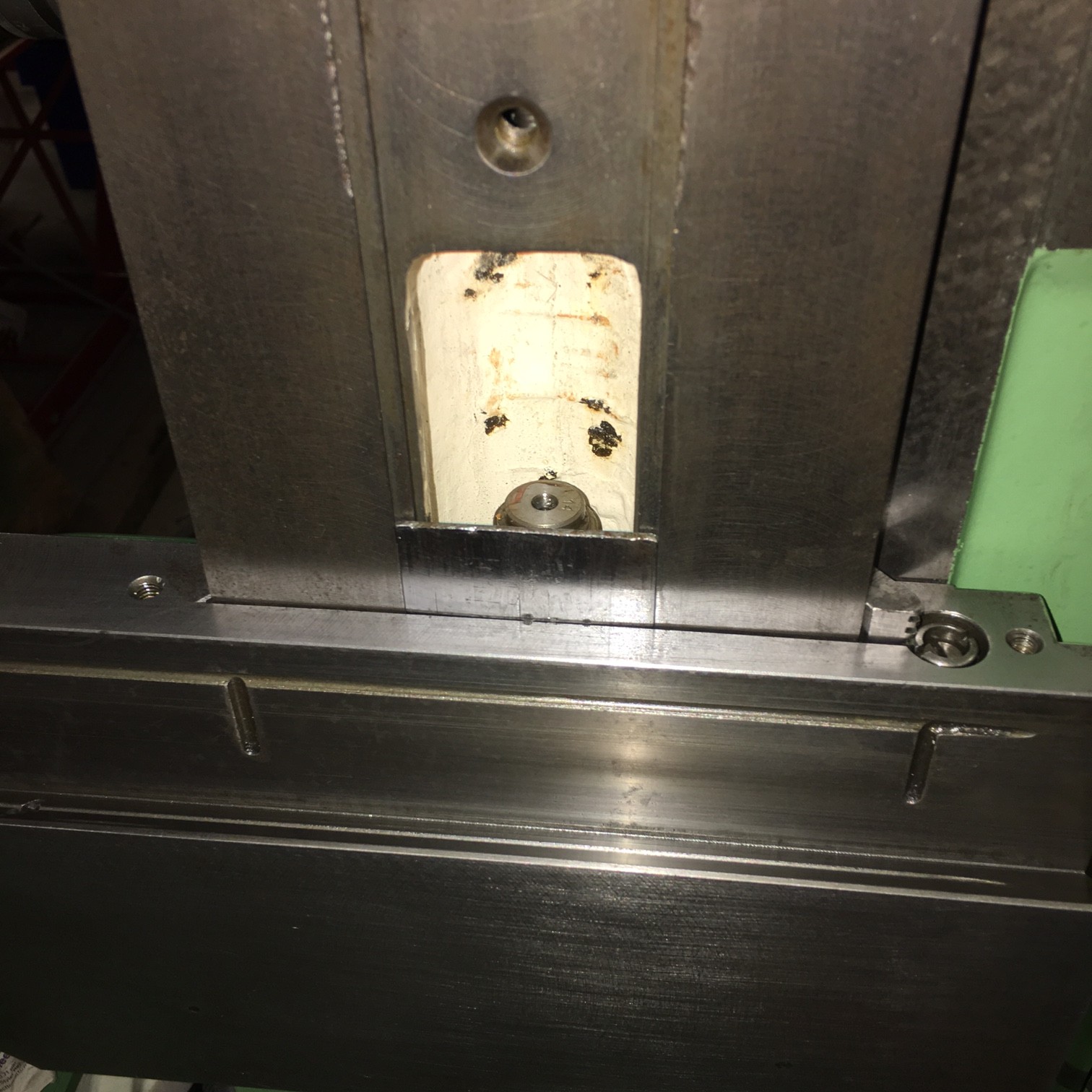
After a little deliberation I decided that to fit the carriage, I would use the column lower blanking plate as a retainer for the ‘scraper & spring’. This is the thin plate in the centre of the photo below. I then left the nut loose on the top of the main vertical screw and fitted the carriage with the jib loose.

IMG_2693

It was then posssible to lift the carriage without worrying about the scraper falling out whilst I positioned the nut in line with the cap head retaining screw. It was a relatively straighforward proceedure. All that was then required was to engage the screw with the nut and then do some initial adjustments. Below is the point where, with decent light, yu can align the saddle with the nut. Once in view it is easily aligned to fit the socket head bolt.


IMG_2712

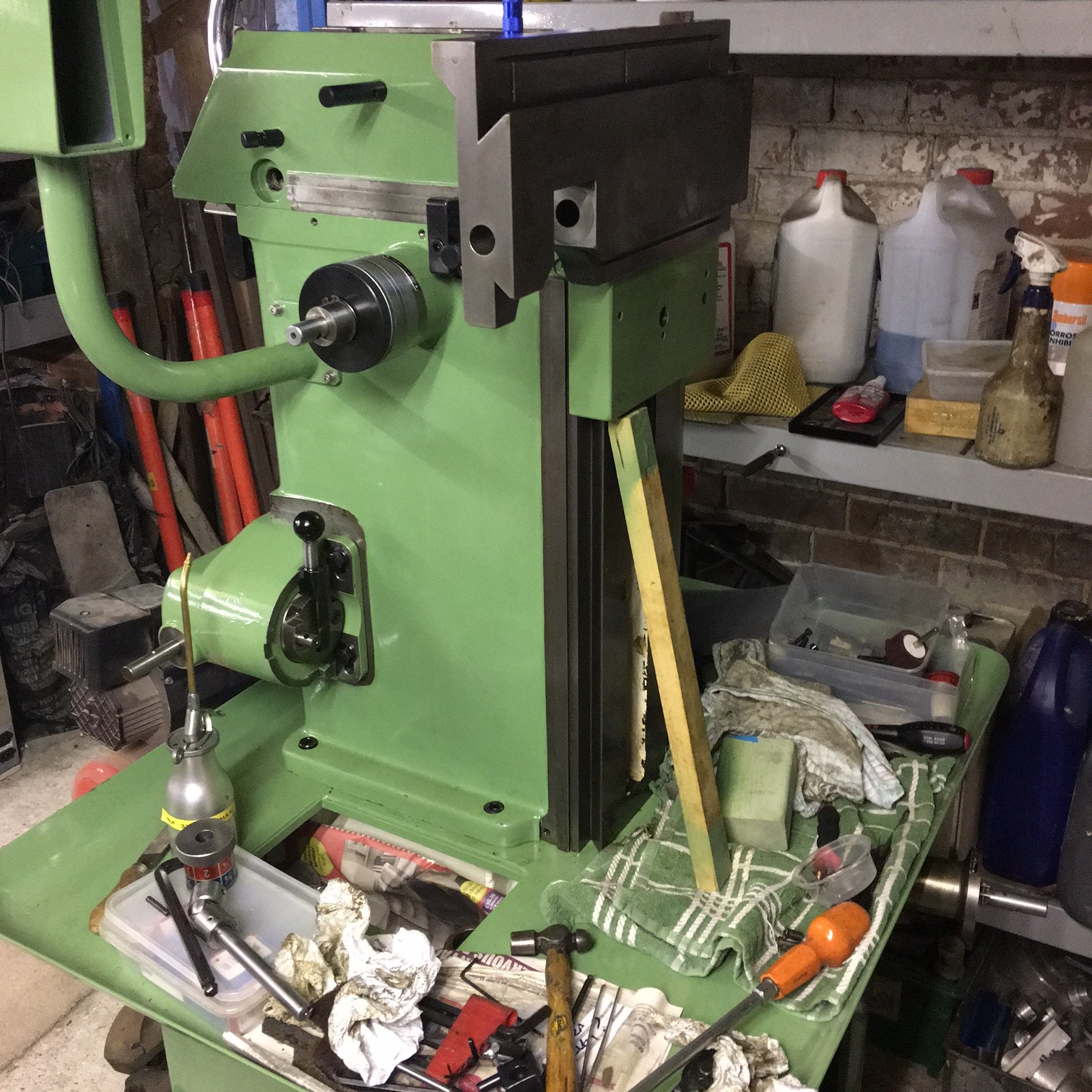
Below is the assembled carriage.

IMG_2692

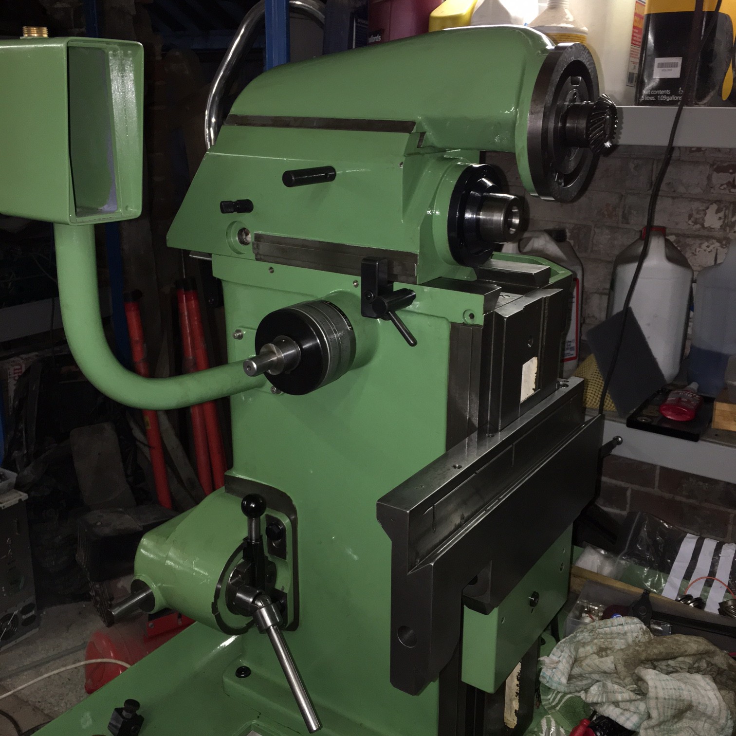
I then put the vertical head on the machine – mainly to get it out of the way!!

IMG_2698

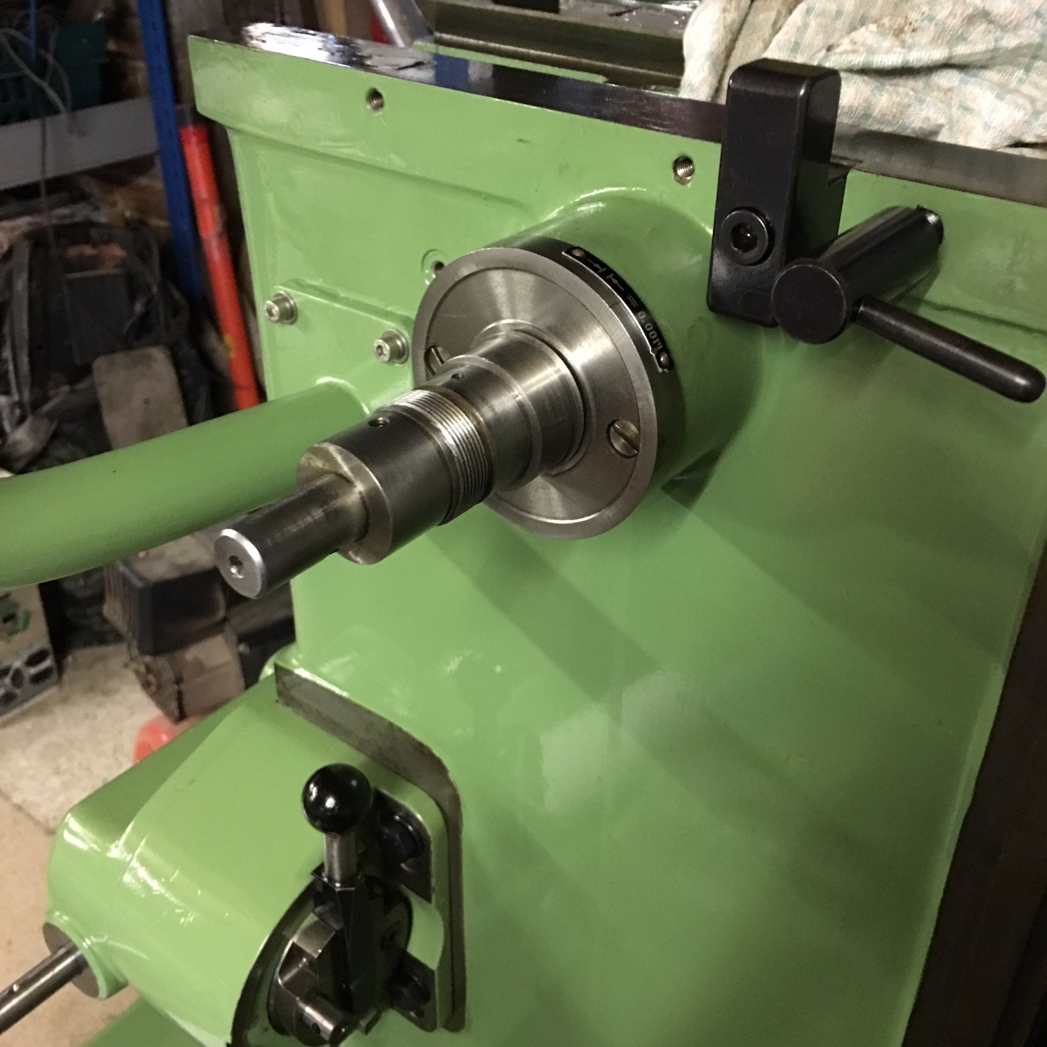
When I was masking up I wan’t sure if the edge of the vertical head was painted. I can now see it was but I shall leave it as is.

IMG_2699

The next stage will be to clean up the slide apron and then refit.

Z carriage

After fitting the horizontal head, I decided the main carriage should be fitted. What I did was to lift the carriage onto the column and steady with piece of wood as shown below. The jib adjuster was then fitted and adjusted to take up most play but still allow me to easily slide the carriage up and down.

IMG_2685

The wood was just long enough to allow fitting of the piece shown by the serial number as below. It was then possible to lower the carriage 10mm to retain this strip and its corresponding spring. (I have no idea what this strip does. Is it a sort of wiper?

IMG_2688

The problem that then occurs is that you cant fit the carriage over the z screw nut! Removing the jib then allows you to fit the carriage over the nut BUT you then lose the strip and spring. So – a little deliberation is called for and I will return with the answer!

Horizontal section rebuild

With things starting to come together, it is time to put the main horizontal drive onto the top casting. Of course, having heaved the this drive unit onto the casting I then realised it needed the drive fitting. Fortunately the casting slides far enough forward to allow this. Once this was fitted into place, then the side spindle could be fitted. You will spot from the photo below that I got a bearing shim in the wrong place and this stopped the bevel gear going back far enough to the rear of the machine. The result – the  side spindle would not go in far enough!

IMG_2675

Fitting the side spindle was straightforward once the spindle above was correctly installed,  although most burrs had to be cleaned up a little to allow easy installation into the casting.

The jib piece was fitted and adjusted to take up most play. Once the machine is fully built I will oil and make all the necessary adjustments.

IMG_2669

As you will see, my machine has dual dials – Metric and Imperial – which is a useful addition and one I have not seen before. The dials are mounted on an extension arbor to the main shaft.

IMG_2670

Below is a photograph of the head slid back. The covers will be re-painted black in due course!!

IMG_2671

The head was slid back and the bracket that holds the screw fitted.

IMG_2676


Gearbox painted.

Here we have the gearbox painted and with all masking take removed. It is worth taking a little extra care in masking up to ensure bare surface are left bare – such as the selector ring.

IMG_2667

It doesn’t look too bad – considering I didn’t even prime it!

I now have to decide is the speed selector knob (not shown here) was blacked or not. Some research on photos may high light this.

All the parts that I want sprayed for the moment are done and so it is on to the rebuild pages.

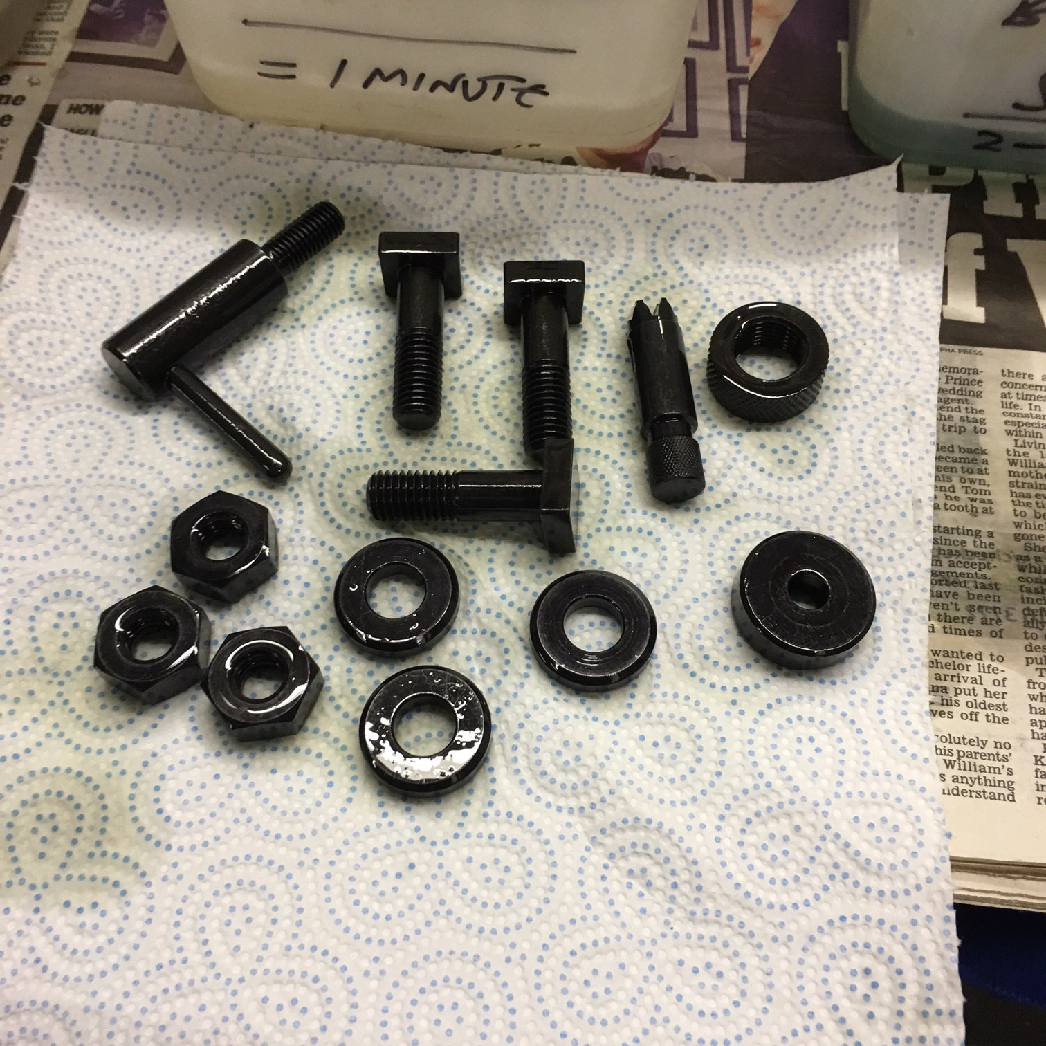
A trial using metal blackening solution

I thought it would be good to transform some of the slightly rusty components back to their blackened glory. Here, I have taken a selection of parts and degreased them.

IMG_2662

Next, cialis usa a session on the 3M fibre wheel to remove rust.

IMG_2665

Then through the process of a blackening solutions.

Items after having been in the oil dispersing solution (after blacking)

Items after having been in the oil dispersing solution (after blacking)

Its not the greatest photo but the results are fabulous and will really add a touch to the refurb. This was a trial and I am very pleased with the results. Now to do the rest.

Cleaning and painting the gearbox.

As you can see, this unit is pretty grubby!

IMG_1030

However, with some degreaser, the unit came up well. The speed selector knob wasa bugger to remove as the locating dimple on the shaft had a severe burr and this caused the knob to lock on the shaft.

IMG_2644 IMG_2646

I don’t have much time at the moment and so this unit will be masked up as a complete unit. I will come back to giving it a full inspection at a later date. So below is said masked item ready for painting.

IMG_2658

A little more priming…

Here we have the vertical head and autofeed control box casting being prepped for primer. They have been filled with a car body type filler ( 2 pack) that is fairly easy to sand. Ideally I would use a filler primer but I have run out and I am reluctant to buy any as we are hopefully moving house soon and I want to transport as little as possible. So an etch primer was used – as this is what I have in abundance.IMG_1029

Once these have cured off we should be ready to put the final coats of 2 pack paint on. I am using an equivalent 2 pack primer to ensure a tough and durable coating. The next job will be to tackle the gearbox for the longitudinal feed. No dought a challenge is in store!